water saving valve

A valve and valve body technology, applied in the field of water-saving valves, can solve problems such as inability to accurately meet production and living needs, adjustment of flow channels that cannot flow, water pressure, and low ability to adjust water flow, so as to avoid excessive injection water pressure. Large, ensure water safety, and avoid water leakage

Active Publication Date: 2022-08-09
二维阀门江苏有限公司
View PDF7 Cites 2 Cited by
  • Summary
  • Abstract
  • Description
  • Claims
  • Application Information

AI Technical Summary

Problems solved by technology

[0006] In order to make up for the deficiencies of the existing technology and solve the problem that the existing valves cannot adjust the flow channel of the water flow during use, the punching capacity of the original pressurized water is wasted, and the ability to adjust the water pressure and water flow is low. Finally, it is impossible to determine the pressure of the water flow, and it cannot accurately meet the needs of production and life, resulting in poor energy-saving effects. A water-saving valve proposed by the present invention

Method used


Image

  • water saving valve
  • water saving valve
  • water saving valve

Examples


Embodiment

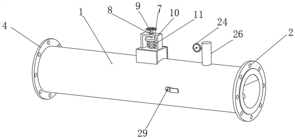
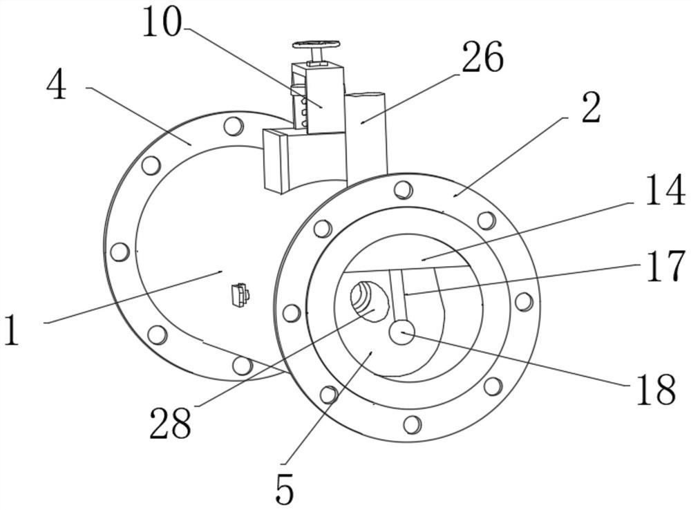
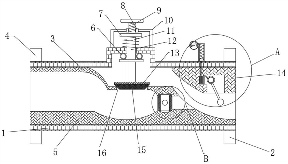
[0032] like Figure 1 to Figure 7 As shown, a water-saving valve according to the present invention includes a valve body 1, a first flange 2 and a second flange 4, and the two ends of the valve body 1 are respectively installed with a first flange 2 and a second flange 4; the two ends of the valve body 1 are respectively installed with the first flange 2 and the second flange 4, the inner wall of the valve body 1 is correspondingly installed with the first limit block 3 and the second limit block 5, the first limit A gap 16 is formed between the block 3 and the second limit block 5. A transfer groove 31 is opened inside the second limit block 5, and a transfer ball 32 is installed in the inside of the transfer groove 31 through the rotating shaft 29. The inside of the transfer ball 32 A diversion hole 30 is provided, an annular groove is formed on the groove wall of the transfer groove 31, and a sealing ring 33 is arranged inside the annular groove. The sealing ring 33 is tan...


PUM


Abstract

The invention belongs to the technical field of water-saving valves, in particular to a water-saving valve, comprising a valve body, a first flange and a second flange, wherein the inner wall of the valve body is provided with a first limit block and a second flange correspondingly up and down. Two limit blocks, the inside of the transfer ball is provided with a diversion hole. Since the opposite surfaces of the second limit block and the first limit block are both set as arc surfaces, the water flow enters the valve body and forms at the front end of the gap. In the slow flow area, avoid excessive spray water pressure and ensure water safety. When high-pressure water flow is required, the transfer ball rotates, and the guide hole is rotated to be parallel to the discharge hole, so that the two sides of the second limit block are connected. Realizing the direct flow of water can improve the water pressure of the jet, better adjust the water flow speed, and meet the needs of life. The pressure gauge is displayed to determine the size of the water pressure and whether it can meet the needs of production and life. The water pressure can be adjusted to facilitate the control of water pressure and water flow, and to achieve the demand for energy-saving water.

Description

technical field [0001] The invention belongs to the technical field of water-saving valves, in particular to a water-saving valve. Background technique [0002] The faucet water-saving valve is mainly used in conjunction with plumbing equipment such as faucets, urinal flushing valves, and sanitary ware, and the water-saving rate is about 50% under 0.3MPa water pressure; [0003] There are also some technical solutions about parts recovery in the prior art. For example, a Chinese patent with an application number of CN110219997B discloses a water-saving valve. The present invention can adjust the water pressure to control the outflow of water per unit time. It can effectively change the traditional faucet with excessive water flow, save water resources, and use the up and down movement of the extrusion block to further adjust the speed of the water flow, so that the water can be discharged in a rapid and slow way, which does not affect the use of users, and at the same time ...

Claims


Application Information

Patent Timeline
Patent Type & Authority Patents(China)
IPC IPC(8): F16K1/02F16K1/36F16K5/06F16K27/00F16K37/00
CPCF16K1/02F16K1/36F16K27/00F16K37/005F16K5/06F16K5/0605F16K5/0647Y02A20/40
Inventor 祁吉庆徐育林
Owner 二维阀门江苏有限公司
Why Eureka
Try Eureka