Pipe fitting pressing sleeve perforating machine and using method thereof

A technology of pressing sleeve and punching machine, applied in the direction of boring/drilling, drilling/drilling equipment, parts of boring machine/drilling machine, etc. Reliability requirements, avoidance of control devices, effect of ease of use

Inactive Publication Date: 2022-02-15
杭州联发管业科技有限公司
View PDF0 Cites 1 Cited by
  • Summary
  • Abstract
  • Description
  • Claims
  • Application Information

AI Technical Summary

Problems solved by technology

[0003] During the drilling process of the original pipe fitting punching machine, it is necessary to manually place the pipe fitting on the fixing fixture, then fix it, punch the hole, and then put the next pipe fitting on the fixing fixture in sequence. It is firm, causing the pipe fittings to deviate, which reduces the accuracy of drilling and reduces the efficiency
[0004] Secondly, the power runs on the belt, and there is noise, which will cause a certain degree of damage to the human eardrum. When punching holes, the height will be adjusted manually, and the holes will be punched manually. This process has low safety performance and greatly affects the safety of personnel. The hidden dangers will cause serious consequences and economic losses at any time, and the safety performance is low

Method used


Image

  • Pipe fitting pressing sleeve perforating machine and using method thereof
  • Pipe fitting pressing sleeve perforating machine and using method thereof
  • Pipe fitting pressing sleeve perforating machine and using method thereof

Examples


Embodiment 1

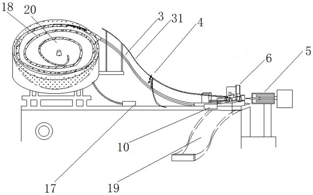
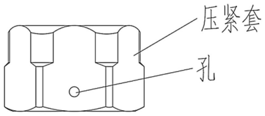
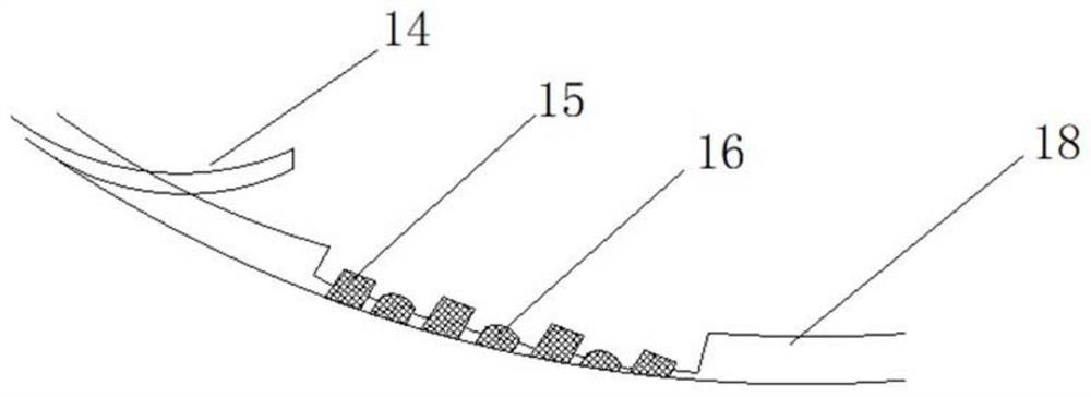
[0051] Embodiment 1. The pipe fitting compression sleeve punching machine is used for automatic feeding and punching of the compression sleeve used for bellows joints. The compression sleeve is a nut type hardware, such as figure 2 As shown, the inner diameter of the top surface is D 1 , the inner diameter of the bottom surface is D 2 , the outer diameter is D, the height is H, and H1 2 , the pipe fitting compression sleeve punching machine includes a compression sleeve feeding vibration plate, a compression sleeve screening mechanism, a feeding mechanism and a compression punching device; the vibration plate technology used in the compression sleeve feeding vibration plate includes a conical hopper 20. Pulse electromagnet 17, spiral track 18, spiral track 18 is arranged spirally along the inner wall of the conical hopper 20, the width of the spiral track 18 is slightly larger than the outer diameter of the compression sleeve, and a compression sleeve is provided on the spira...


PUM


Abstract

The invention discloses a pipe fitting pressing sleeve perforating machine. The pipe fitting pressing sleeve perforating machine comprises a pressing sleeve feeding vibration disc, a feeding mechanism and a pressing perforating device which are sequentially arranged; the pressing sleeve feeding vibration disc comprises a conical hopper, a spiral track is arranged in a spiral rising mode along the inner wall of the conical hopper, the feeding mechanism comprises a linear feeding track, an inlet of the linear feeding track is connected with an outlet of the spiral track, an outlet of the linear feeding track is lower than the inlet, and a push plate is arranged at the outlet of the linear feeding track; and the pressing perforating device comprises a pressing mechanism and a drilling device, the pressing mechanism is arranged on the pushing track of the pushing plate, and the drilling device is adjacent to the pressing mechanism. The invention further provides a using method of the pipe fitting pressing sleeve perforating machine. According to the invention, a reliable photoelectric sensor and delay control are adopted, sequential operation of a plurality of devices is realized, a complicated control device is prevented from being adopted, and the perforating machine has the characteristics of convenience and reliability.

Description

technical field [0001] The invention relates to the technical field of corrugated pipe processing equipment, in particular to a punching machine for a compression sleeve of a pipe fitting and a use method thereof. Background technique [0002] At present, in the process of producing pipe fittings, it is necessary to punch holes in the compression sleeve of the pipe fittings to better detect whether there is any air leakage. One of the core steps is to punch holes in the pipe fittings. For the size of the aperture and the depth of the aperture, both There are strict requirements. [0003] During the drilling process of the original pipe fitting punching machine, it is necessary to manually place the pipe fitting on the fixing fixture, then fix it, punch the hole, and then put the next pipe fitting on the fixing fixture in sequence. If it is firm, it will lead to the misalignment of the pipe fittings, which will reduce the accuracy of drilling and reduce the efficiency. [0...

Claims


Application Information

Patent Timeline
Patent Type & Authority Applications(China)
IPC IPC(8): B23B41/00B23B47/00B23Q3/06B23Q3/154B23Q7/08B23Q7/10
CPCB23B41/00B23B47/00B23Q3/062B23Q3/154B23Q7/08B23Q7/10
Inventor 凡思军凡思义
Owner 杭州联发管业科技有限公司
Why Eureka
Try Eureka