Single-side wind-proof and sound-proof barrier device for bridge

A bridge-use, wind-acoustic technology, applied to noise-absorbing devices, buildings, etc., can solve problems such as hidden dangers, sound barriers without wind-proof function, and easy to be blown down by strong winds, so as to avoid wind damage, improve wind-proof effect, increase The effect of high ventilation efficiency

Active Publication Date: 2022-02-15
CHONGQING JIAOTONG UNIVERSITY
View PDF7 Cites 0 Cited by
  • Summary
  • Abstract
  • Description
  • Claims
  • Application Information

AI Technical Summary

Problems solved by technology

[0003]Aiming at the deficiencies of the above-mentioned technologies, the purpose of the present invention is to provide a single-side windproof sound barrier device for bridges, which is used to solve the problem of installing on one side of the bridge in the prior art. The sound barrier does not have the function of windproof, and it is easy to be blown down by strong wind, which brings safety hazards

Method used


Image

  • Single-side wind-proof and sound-proof barrier device for bridge
  • Single-side wind-proof and sound-proof barrier device for bridge
  • Single-side wind-proof and sound-proof barrier device for bridge

Examples


Embodiment 1

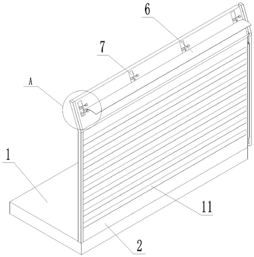
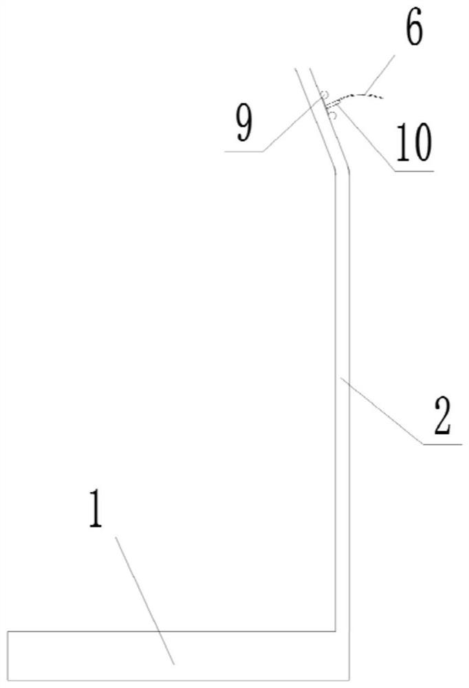
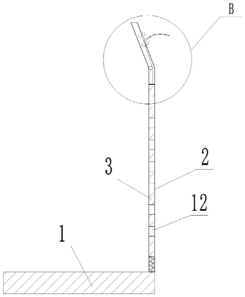
[0033] Such as Figure 1 to Figure 5As shown, a single-side windproof sound barrier device for a bridge includes an outer shell 2, the outer shell 2 is fixed on one side edge of the bridge deck 1, the interior of the outer shell 2 is hollow, and the outer shell 2 The inner surface and the outer surface of 2 are provided with the first ventilation groove 11 distributed in the height direction, and the inside of the outer shell 2 is provided with an inner plate 3 slidingly connected with the upper and lower sides, and the inner plate 3 is provided with the first A ventilation slot 11 and a second ventilation slot 12 with the same size and shape, the first ventilation slot 11 and the second ventilation slot 12 are staggered, and the upper outer surface of the outer shell 2 is evenly provided with a number of through slots 7 in the length direction. The slot 7 is provided with a windshield 6 which is slidably connected thereto, and the windshield 6 is provided with a first stay co...

Embodiment 2

[0044] The difference between Embodiment 2 and Embodiment 1 is that both sides of the upper part of the outer shell are provided with windshields, through grooves, and the first or second pull cords, which has the advantage of making the sound barrier When the inner and outer sides of the shell are blown by strong winds, the windproof function can be triggered. Specifically, the inner surface of the outer shell 2 is provided with a chute and a windshield 6 corresponding to the position on the outer surface, and the windshield 6 is provided with a second windshield. Two stay ropes, the two ends of the second stay rope are respectively connected to the upper ends of the windshield 6 and the inner plate 3, if the geographical position on both sides of the bridge does not have the conditions for keeping out the wind, then both sides are provided with chute and windshield. Plate 6 and the first stay cord 14 or the second stay cord, no matter which side the wind blows from the two si...


PUM


Abstract

The invention relates to the technical field of bridge devices, in particular to a single-side wind-proof and sound-proof barrier device for a bridge. The device comprises an outer-layer shell, the outer-layer shell is fixed to the edge of one side of a bridge floor, the outer-layer shell is hollow, first ventilation grooves distributed in the height direction are formed in the inner surface and the outer surface of the outer-layer shell correspondingly, and an inner plate slidably connected with the upper portion and the lower portion of the outer-layer shell is arranged in the outer-layer shell; the inner plate is provided with second ventilation grooves which are the same as the first ventilation grooves in size and shape, the first ventilation grooves and the second ventilation grooves are formed in a staggered mode, a plurality of through grooves are evenly formed in the outer surface of the upper portion of the outer layer shell in the length direction, and the through grooves are provided with wind shields connected with the through grooves in a sliding mode; first pull ropes with the number corresponding to that of the through grooves are arranged on the wind shield, and one end of each first pull rope is fixedly connected to the wind shields. The technical scheme is used for solving the problem that the sound barrier in the prior art does not have a windproof function and is very easy to blow down by strong wind to cause potential safety hazards.

Description

technical field [0001] The invention relates to the technical field of bridge devices, in particular to a single-side windproof sound barrier device for bridges. Background technique [0002] A sound barrier is a facility between the sound source and the receiver to block the propagation of sound waves, thereby reducing the impact of noise in the area where the receiver is located. With the continuous development of my country's traffic construction, more and more bridges have been built, and a few have crossed residential areas and commercial office areas. Therefore, vehicles driving on bridges have brought noise pollution to the surrounding areas, and the height of bridges is usually high. The wind is strong. If there is a residential area on one side of the bridge, the general and effective treatment measure is to install a sound barrier on one side of the bridge. The engineering acoustic effect of the sound barrier is usually determined by the height of the sound barrier....

Claims


Application Information

Patent Timeline
Patent Type & Authority Applications(China)
IPC IPC(8): E01F8/00
CPCE01F8/0017E01F8/0023
Inventor 刘浪罗浩马长龙施文辉徐漫菲
Owner CHONGQING JIAOTONG UNIVERSITY
Why Eureka
Try Eureka