
System and method for rapidly detecting position of connector

A detection system and connector technology, used in measuring devices, material analysis by optical means, instruments, etc., can solve the problems of difficult daily maintenance, easy to be contaminated with dust, complicated operation, etc., to shorten the position matching time and protect the safety. , the effect of simplifying the matching step

Pending Publication Date: 2022-02-15
北京邦卓尔微电子有限公司
View PDF0 Cites 0 Cited by
  • Summary
  • Abstract
  • Description
  • Claims
  • Application Information

AI Technical Summary

Problems solved by technology

[0005] 1) When the size of the same type of test piece changes, in order to make the image clear, the deformation uniform and suitable, and the position correction more accurate, it is necessary to repeatedly adjust the distance and position of the top probe, the test piece and the beam splitter prism, and the focal length of the CCD, so that the The operation of the scheme matching method becomes very cumbersome, takes a long time and is inefficient;
[0006] 2) In actual use, since the beam splitting prism is a high-precision optical device, it is easy to be contaminated with dust and other pollutants, making daily maintenance difficult. After each maintenance, it needs to be re-matched, and the operation is also very cumbersome

Method used


Image

  • System and method for rapidly detecting position of connector
  • System and method for rapidly detecting position of connector
  • System and method for rapidly detecting position of connector

Examples


Embodiment Construction

[0026] The technical solutions in the embodiments of the present invention are clearly and completely described below in conjunction with the accompanying drawings in the embodiments of the present invention. Obviously, the described embodiments are only part of the embodiments of the present invention, not all of them. Based on the embodiments of the present invention, all other embodiments obtained by persons of ordinary skill in the art without making creative efforts belong to the protection scope of the present invention.

[0027] In the following description, a lot of specific details are set forth in order to fully understand the present invention, but the present invention can also be implemented in other ways different from those described here, and those skilled in the art can do it without departing from the meaning of the present invention. By analogy, the present invention is therefore not limited to the specific examples disclosed below.

[0028] Such as image ...


PUM


Abstract

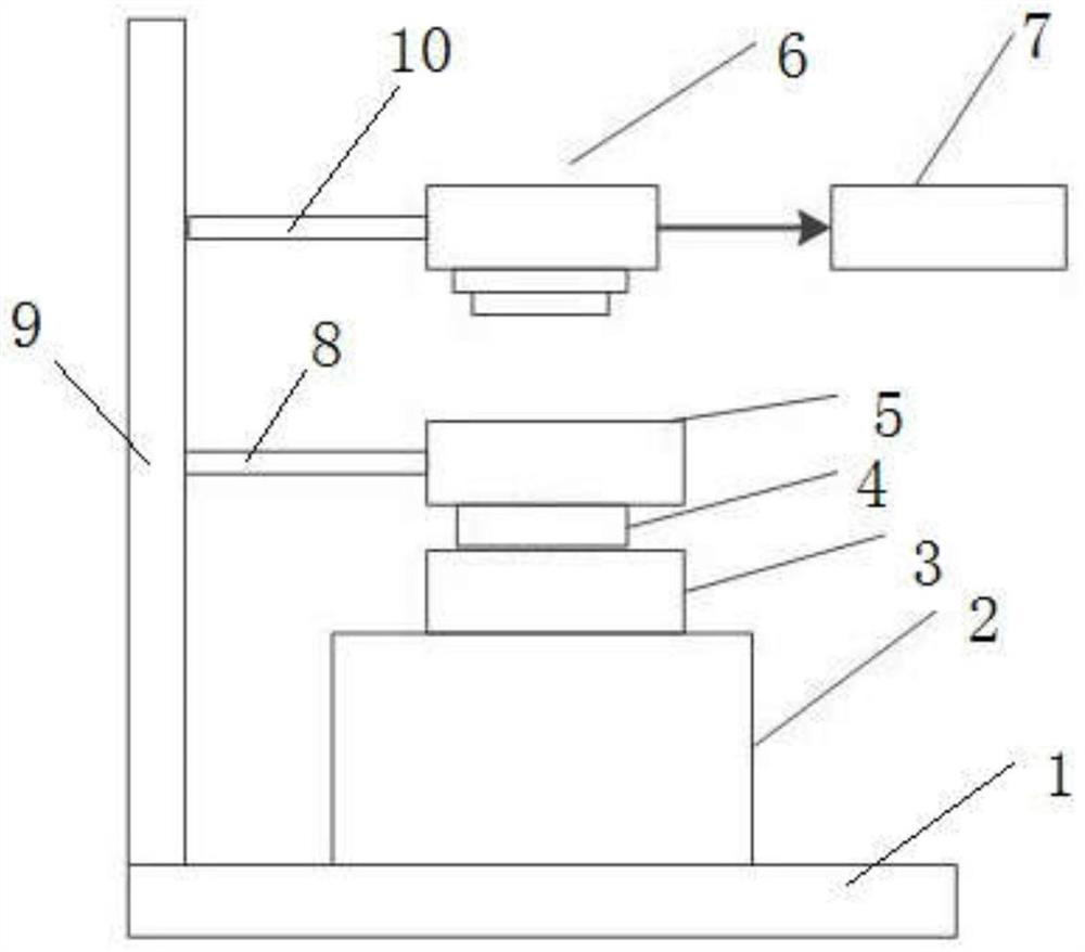
The invention discloses a system and a method for rapidly detecting the position of a connector. The detection system comprises a supporting base, a precise three-dimensional displacement table is arranged on the supporting base, a connector clamp is fixed on the precise three-dimensional displacement table, and the connector clamp is used for fixing a detected piece; a pin position calibration mold fixing device is fixed on the upper side of the detected piece, and a calibration mold is fixed on the lower side of the mold fixing device; a high-definition camera is arranged on the upper side of the fixing device and is used for acquiring image information of the detected piece and the connector fixture; and the test computer is connected with the signal output end of the high-definition camera, and image information collected by the high-definition camera is transmitted to the test computer to be processed. The detection system and method have the advantages of being convenient to use, capable of shortening test time, high in matching efficiency, good in safety and the like.

Description

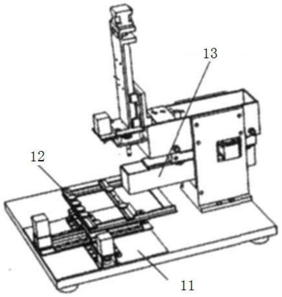
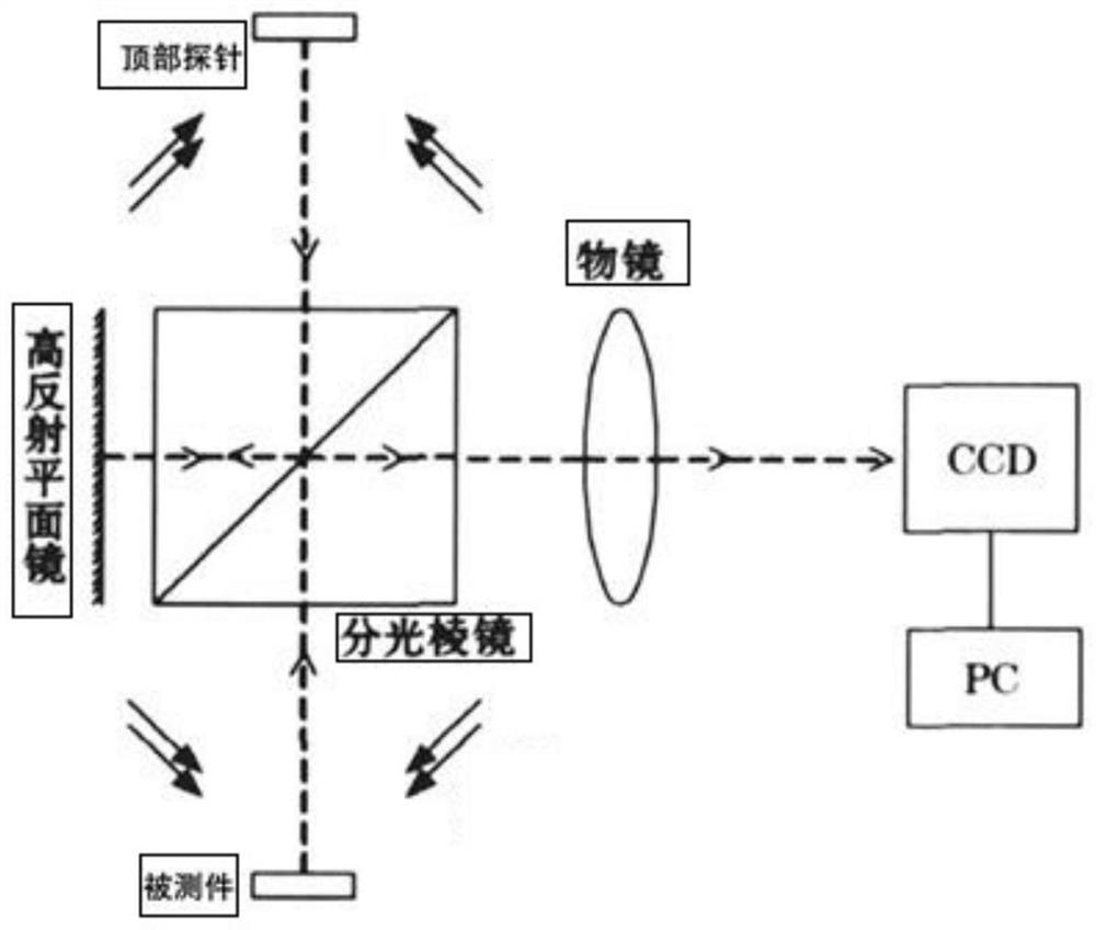
technical field [0001] The invention relates to the technical field of connector detection devices, in particular to a rapid detection system and detection method for a connector position. Background technique [0002] Since a certain connector is a highly precise conductive device, and the surface of the pin is gold-plated, it is easy to be scratched. Usually, when measuring the insulation resistance and conduction resistance between the pins of the connector (hereinafter referred to as "device under test") , in order to prevent the pins of the DUT from being scratched, use the method of contacting the probes with the DUT pins. [0003] After fixing the DUT with the DUT jig, the vision system is used to accurately align the DUT with the top probe, and then perform subsequent measurements. The program exactly matches the implementation structure as figure 1 As shown, it is mainly composed of the workbench, the fixture under test and the vision system (such as figure 2 sh...

Claims


Application Information

Patent Timeline
Patent Type & Authority Applications(China)
IPC IPC(8): G01N21/01
CPCG01N21/01G01N2021/0112
Inventor 孙日东纪玲燕
Owner 北京邦卓尔微电子有限公司
Learn More