
Optical fiber cable sheath fracture early warning method

An optical fiber cable and sheath technology, applied in the field of image processing, can solve the problems of accelerating the deterioration of terminal insulation materials, leaving air gaps on the main insulation surface, and terminal insulation breakdown.

Active Publication Date: 2022-02-15
山东鹰联光电科技股份有限公司
View PDF9 Cites 13 Cited by
  • Summary
  • Abstract
  • Description
  • Claims
  • Application Information

AI Technical Summary

Problems solved by technology

During the installation of the cable terminal, due to the strict control of the construction time, when using a cutter for the outer semiconductive layer of the glass cable, because the cutting depth of the cutter is not easy to control, air gap defects are often left on the main insulating surface in the actual glass process
The distorted electric field at the air gap defect will cause the partial discharge of the terminal, which will cause ablation and carbonization at the air gap defect, accelerate the deterioration of the terminal insulation material, and eventually lead to the breakdown of the terminal insulation, so it is necessary to detect the defect of the cable terminal
[0003] At present, the detection of cable sheath damage is usually to detect the cracks or air gap defects on the surface of the sheath, but not to detect the irregular defects of ablation carbonization caused by air gap defects

Method used


Image

  • Optical fiber cable sheath fracture early warning method
  • Optical fiber cable sheath fracture early warning method
  • Optical fiber cable sheath fracture early warning method

Examples


Embodiment Construction

[0046] In order to further explain the technical means and effects adopted by the present invention to achieve the intended purpose of the invention, the specific implementation methods, The structure, characteristics and effects thereof are described in detail as follows. In the following description, different "one embodiment" or "another embodiment" do not necessarily refer to the same embodiment. Furthermore, the particular features, structures, or characteristics of one or more embodiments may be combined in any suitable manner.

[0047] Unless otherwise defined, all technical and scientific terms used herein have the same meaning as commonly understood by one of ordinary skill in the technical field of the invention.

[0048] The embodiment of the present invention provides a specific implementation method of a method for early warning of fiber optic cable sheath rupture, and the method is applicable to the scene of early warning of cable sheath rupture. Use the RGB ca...


PUM


Abstract

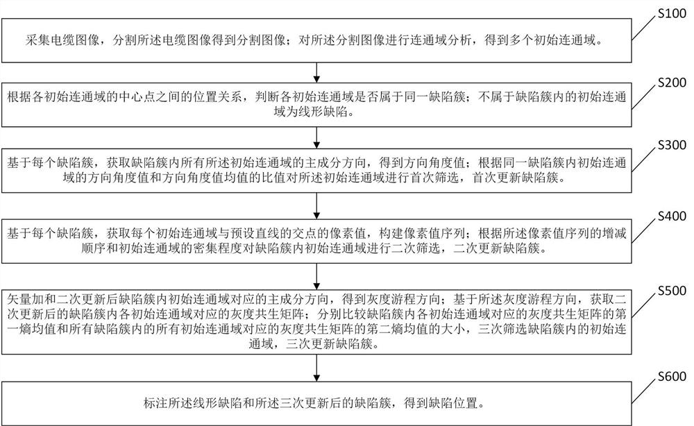
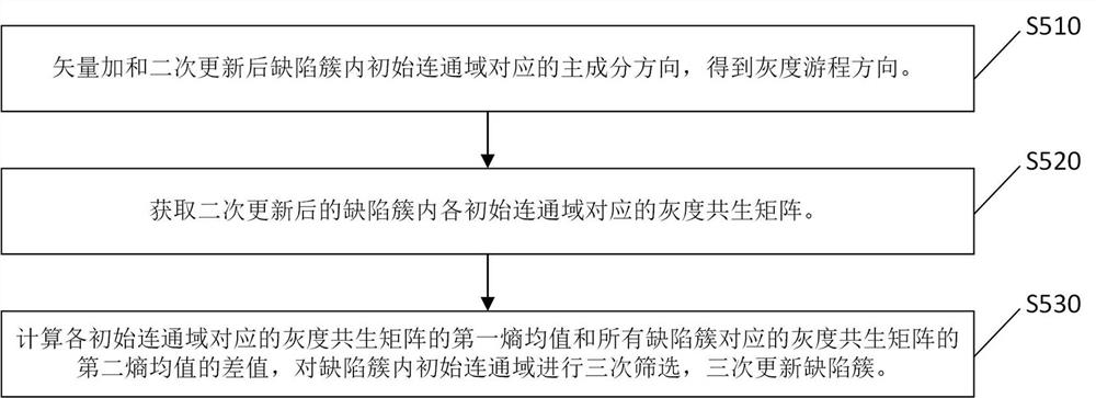
The invention relates to the technical field of image processing, and concretely relates to an optical fiber cable sheath fracture early warning method. The method comprises the following steps: firstly collecting a cable image, and obtaining a plurality of initial connected domains; obtaining a plurality of defect clusters according to the position relation of the central points of the initial connected domains, judging the initial connected domain which does not belong to the defect cluster as a linear defect; obtaining principal component directions of all initial connected domains in the defect cluster, and screening the initial connected domains in the defect cluster for the first time; on the basis of each defect cluster, according to the increase and decrease sequence of the pixel value sequence of each initial connected domain and the density of the initial connected domains, secondarily screening the initial connected domains in the defect cluster; obtaining a gray level co-occurrence matrix of each initial connected domain in the defect cluster; according to the entropy mean value of the gray-level co-occurrence matrix, screening initial connected domains in the defect cluster for three times; and marking linear defects and defect clusters after three times of screening to obtain defect positions. According to the embodiment of the invention, irregular defects are detected, and the purposes of cable defect detection and early warning are achieved.

Description

technical field [0001] The invention relates to the technical field of image processing, in particular to a method for early warning of fiber optic cable sheath rupture. Background technique [0002] Cable terminals are widely used in urban distribution network systems. Due to the strict control of the construction time during the installation of the cable terminal, when using a cutter for the outer semiconductive layer of the glass cable, since the cutting depth of the cutter is not easy to control, air gap defects are often left on the main insulating surface during the actual glass process. The distorted electric field at the air gap defect will cause the partial discharge of the terminal, which will cause ablation and carbonization at the air gap defect, accelerate the deterioration of the terminal insulation material, and eventually lead to the breakdown of the terminal insulation. Therefore, it is necessary to detect the defect of the cable terminal. [0003] At prese...

Claims


Application Information

Patent Timeline
Patent Type & Authority Applications(China)
IPC IPC(8): G06V10/25G06V10/26G06V10/764G06K9/62G06T7/00
CPCG06T7/0002G06F18/2415
Inventor 束建磊刘建强
Owner 山东鹰联光电科技股份有限公司
Learn More