
Device and method for generating photo-generated six-frequency-multiplication phase-coded microwave signal

A technology of microwave signal and phase encoding, which is applied in phase-modulated carrier systems, optical fiber transmission, electrical components, etc., can solve problems such as complex structures, lower system stability, and difficult phase-encoded microwave signals, achieving easy implementation, low cost, Simple structure of the device

Pending Publication Date: 2022-02-15
JIANGSU NANFANG COMM TECH
View PDF5 Cites 0 Cited by
  • Summary
  • Abstract
  • Description
  • Claims
  • Application Information

AI Technical Summary

Problems solved by technology

For example, the frequency multiplication factor of the microwave signals they generate is double or quadruple, and it is difficult to generate higher-frequency phase-encoded microwave signals; the above-mentioned systems generally use multiple optoelectronic modulators (including MZM modulators and polarization modulators), This leads to a relatively complex structure and high cost; in addition, some solutions also use optical filters or fiber Bragg gratings, which will limit the frequency tuning range of the generated microwave signals and also reduce the stability of the system

Method used


Image

  • Device and method for generating photo-generated six-frequency-multiplication phase-coded microwave signal
  • Device and method for generating photo-generated six-frequency-multiplication phase-coded microwave signal
  • Device and method for generating photo-generated six-frequency-multiplication phase-coded microwave signal

Examples


Embodiment Construction

[0044] The following will clearly and completely describe the technical solutions in the embodiments of the present invention. Obviously, the described embodiments are only some of the embodiments of the present invention, rather than all the embodiments. Based on the embodiments of the present invention, all other embodiments obtained by persons of ordinary skill in the art without making creative efforts belong to the protection scope of the present invention.

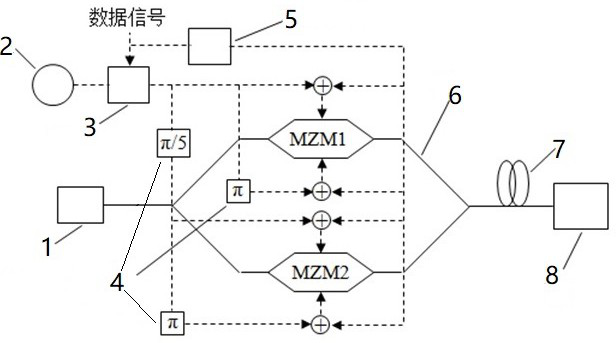
[0045] see figure 1 , the embodiment of the present invention includes:

[0046] An optically generated six-fold frequency phase-encoded microwave signal generator, comprising: a laser 1, a microwave signal generator 2, an electrical phase modulator 3, a phase shifter 4, an electrical gainer 5, a parallel MZM modulator 6, and a single-mode fiber 7 and a photodetector 8, wherein the parallel MZM modulator 6 may employ a parallel Mach-Zehnder modulator MZM,

[0047] The laser 1, the parallel modulator 6, the single-m...


PUM


Abstract

The invention discloses a device and a method for generating a photo-generated six-frequency-multiplication phase-coded microwave signal, and the method comprises the steps: carrying out the modulation of a microwave signal through a parallel MZM modulator, adding an upper signal and a lower signal of the parallel modulator to generate a 2k + 1-order sideband, setting a modulation index m to enable the + / -1-order sideband to be zero, adjusting a phase shifter to set the phase difference of MZM1 and MZM2 microwave drive signals to be pi / 5, outputting + / -3 order sidebands; adding a microwave signal modulated by a data phase and a gained data signal to drive an MZM1 and an MZM2, setting an electric phase modulator modulation parameter and an electric gainer gain coefficient, so that only one sideband of the optical microwave signal carries data, and the sideband phase changes along with the data; and the positive third-order sideband and the negative third-order sideband of the receiving end beat frequency at a photoelectric detector PD to generate a six-frequency-multiplication phase-coded microwave signal. By means of the mode, the six-frequency-multiplication phase-coded microwave signal is generated only through the single parallel MZM modulator, and the requirements of modern radar or wireless communication for high carrier frequency, large bandwidth and wide tuning signals are met.

Description

technical field [0001] The invention relates to the technical field of photoelectric signal processing methods, in particular to a method for generating six-fold frequency phase-encoded microwave signals using optical technology. Background technique [0002] Phase-encoded microwave signals are commonly used in modern radar systems and wireless communications. Although the method of phase encoding microwave signals using electronic technology is relatively mature, it is difficult to meet the requirements of modern radar or wireless communication for high carrier frequency, large bandwidth and wide tuning signal due to the limitation of "electronic bottleneck". The use of optical technology to generate phase-encoded microwave signals has the advantages of high frequency, broadband, wide tuning range, avoidance of electromagnetic interference and low transmission loss. [0003] With the rapid development of the information society, the working frequency of modern radar and wi...

Claims


Application Information

Patent Timeline
Patent Type & Authority Applications(China)
IPC IPC(8): H04B1/40H04B10/25H04L27/20
CPCH04L27/20H04B1/40H04B10/25
Inventor 石明陈小刚
Owner JIANGSU NANFANG COMM TECH
Learn More