Steering device of ship propeller

A steering device and propeller technology, applied in the direction of steering and steering with propulsion components, can solve the problems of reducing reliability and safety, damage, shortening the service life of motors, etc., to reduce maintenance costs, reduce collision force, and prolong use. effect of life

Pending Publication Date: 2022-02-18
NINGBO HAIBO GRP CO LTD
View PDF12 Cites 0 Cited by
  • Summary
  • Abstract
  • Description
  • Claims
  • Application Information

AI Technical Summary

Problems solved by technology

[0005] The bottom of the ship may encounter obstacles such as reefs during navigation. In order to avoid direct collision between the propeller and obstacles, the steering device is usually rotatably fixed on the hull, and the propeller is connected to the bottom of the steering device. However, Most of the existing mechanical steering devices are fixed on the hull with a snap-in structure (such as using a hook to hang the crossbar). After the obstacle, until the buckle of the steering device is disengaged by the collision force, the propeller can be turned over together with the steering device body (the motor is lifted from the water), so as to prevent the motor of the propeller from being damaged by the obstacle. Although this buckle structure can disengage the buckle when a certain collision force occurs, this disengagement method requires the propeller to be subjected to sufficient collision force before it can be realized. If the force generated by the collision cannot make the buckle disengage, then The motor is subject to direct frontal strong impact, frequent impact will shorten the service life of the motor, especially for the steering device with mechanical transmission structure, the impact and damage will be great, which will reduce the reliability and safety of product use

Method used


Image

  • Steering device of ship propeller
  • Steering device of ship propeller
  • Steering device of ship propeller

Examples


Embodiment Construction

[0034] The present invention will be further described in detail below in conjunction with the accompanying drawings and embodiments.

[0035] This embodiment discloses a steering device of a ship propeller, which can control the rotation direction of the propeller and control the forward direction of the ship.

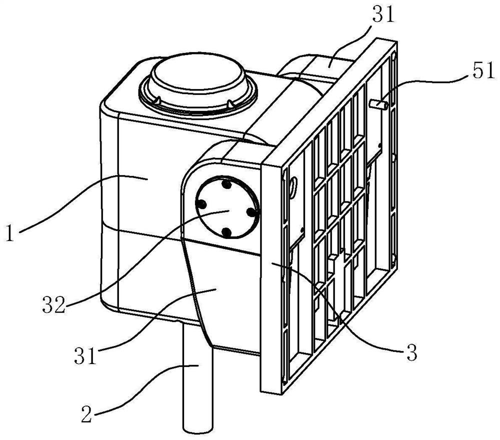
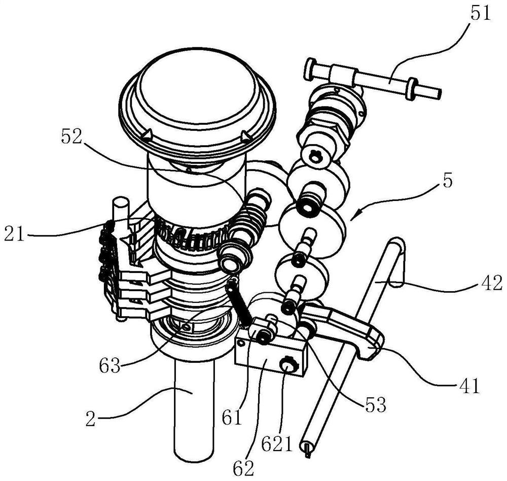
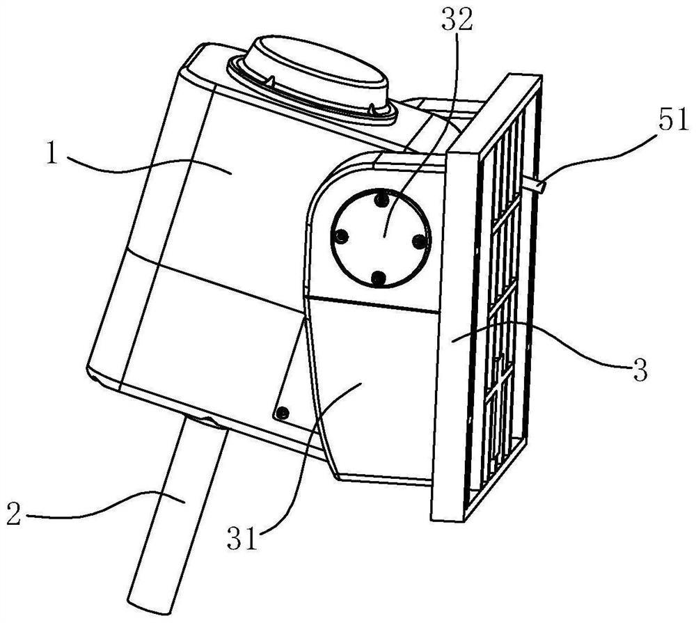
[0036] Such as Figure 1 to Figure 8As shown, the steering device of this embodiment includes a housing 1, a steering spindle 2, a buckle device and a transmission device. The housing 1 can be directly connected to the hull, or can be connected to the hull through the base 3. For the convenience of installation, The base 3 is a flat plate and is fixed on the hull. The base 3 is provided with two side plates 31, and a pivot 32 is fixed between the two side plates 31. The housing 1 is rotatably arranged on the pivot 32, so that the housing 1 Reversible relative to the hull, see image 3 .

[0037] The steering spindle 2 is accommodated in the casing 1 , and one end o...


PUM


Abstract

The utility model discloses a steering device of a ship propeller. The steering device comprises a shell, a steering spindle; a buckling device; the steering device is characterized in that the steering device further comprises a transmission mechanism, the transmission mechanism comprises an input end, a first output end and a second output end, the first output end is in transmission with the steering main shaft, and a cam mechanism is arranged at the second output end; when the rotating angle of the steering main shaft from the zero position is within a set threshold angle [alpha, beta], the buckling device is in a locking state; and when the rotating angle of the steering main shaft from the zero position is beyond the set threshold angle [alpha, beta], the buckling device is in an unlocked state. The steering device has the advantages that the rotation angle threshold value of the steering main shaft is set, stability of the ship during steering is guaranteed (at the moment, the steering device is fixedly connected with the ship body), collision acting force can be effectively weakened in the advancing process (at the moment, the steering device is connected with the ship body in a turnover mode), and a motor of the propeller is prevented from being strongly collided frontally; and the service lives of the motor and the transmission device are prolonged.

Description

technical field [0001] The invention relates to a ship direction control device, in particular to a steering device for a ship propeller. Background technique [0002] The ship propeller is an energy converter in the ship propulsion device, which converts the power generated by the engine into the thrust of the ship to overcome the resistance of the ship navigating in the water and push the ship forward. [0003] There are many types of ship propellers. According to different principles, there are usually propellers, water jet propellers, special propellers, etc. The propellers provide power for the ship to move forward, and changing the direction of the ship is controlled by a steering device that can be linked with the propeller. In the prior art, the commonly used steering devices include electric steering control and mechanical steering control. Realize the steering system of the propeller ship, the steering system includes: steering wheel, set above the hull; angle sen...

Claims


Application Information

Patent Timeline
Patent Type & Authority Applications(China)
IPC IPC(8): B63H25/42
CPCB63H25/42
Inventor 张华军周玉平胡旭刚赵科南叶吉武
Owner NINGBO HAIBO GRP CO LTD
Why Eureka
Try Eureka