Winding packaging device for wrapping film packaging

A technology for stretch film and packaging, which is applied in the field of stretch film packaging devices, and can solve the problems of inconvenient stretch film packaging, inconvenient induction-type automatic cutting operation, and inconvenient multi-sided winding of workpieces. Packaging and other issues

Active Publication Date: 2022-02-18
黄山源点新材料科技有限公司
View PDF9 Cites 1 Cited by
  • Summary
  • Abstract
  • Description
  • Claims
  • Application Information

AI Technical Summary

Problems solved by technology

[0007] The purpose of the present invention is to provide a wrapping wrapping device for stretch film packaging to solve the above-mentioned background technology. The existing wrapping wrapping device is inconvenient to realize the change of the fixed position for multi-sided wrapping and wrapping of the workpiece, and it is inconvenient to maintain the stretching film. It fits the package stably, and at the same time it is inconvenient to perform inductive automatic cutting operation

Method used


Image

  • Winding packaging device for wrapping film packaging
  • Winding packaging device for wrapping film packaging
  • Winding packaging device for wrapping film packaging

Examples


Embodiment 1

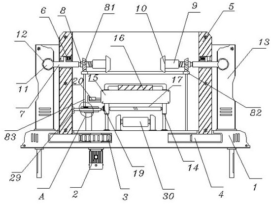
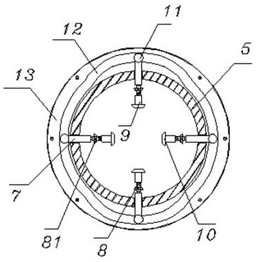
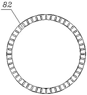
[0042] see Figure 1-4 , including a base 1, a motor 2 is fixed on the bottom of the base 1, and a guide gear 3 is connected to the output end of the motor 2, and a guide gear ring 4 is installed on the outer side of the guide gear 3, and the guide gear ring 4 and the guide gear 3 are embedded installed in the base 1, and the top of the guide tooth ring 4 is fixed with a mounting frame 5, and the mounting frame 5 is movably arranged above the base 1; On the side wall, a reinforcing spring 6 is fixed between the cross bar 7 and the inside of the mounting frame 5, and one end bearing of the cross bar 7 is connected with a mounting rod 8, and one end of the mounting rod 8 is provided with a mounting sleeve 9, and the mounting sleeve One end of 9 is bonded with a fixed block 10, and the fixed block 10 and the mounting sleeve 9 are all located on the inside of the mounting bracket 5, and the other end of the cross bar 7 is fixed with a guide ball 11, and the guide ball 11 is locate...

Embodiment 2

[0044] see figure 1 , Figure 5 Figure 10 , the difference from Embodiment 1 is: the stretch film roll assembly 30, the stretch film roll assembly 30 is installed on the upper end of the middle part of the base 1, and the top of the base 1 is connected with the positioning frame 15 through the elastic telescopic rod 14, and the positioning frame 15 The top is fixed with a heating plate 16, the positioning frame 15 is located above the stretch film roll assembly 30, and positioning rollers 17 are installed on the inner wall of the elastic telescopic rod 14 below the positioning frame 15, and a stretching assembly 18 is installed in the positioning frame 15, positioning The top of the frame 15 is connected with a pressure bar 152 through an elastic telescopic column 151 rotating shaft, and the pressure bar 152 is movably installed at the raised position on the top of the positioning frame 15; the stretching assembly 18 includes a first stretching roller 181 and a second stretc...

Embodiment 3

[0046] see figure 1 and Figure 6-9 , the difference from Embodiment 2 is: the pressure sensor 19, the pressure sensor 19 is fixed on the outside of the elastic telescopic rod 14, and the outside of the positioning frame 15 on the top of the elastic telescopic rod 14 is equipped with an electric push rod 20, and the electric push rod 20 The output end runs through the positioning frame 15 and is connected with a push frame 21, the push frame 21 is movably installed in the positioning frame 15, and the inner wall of the positioning frame 15 is connected with a mounting bar 23 by a return spring 22, and the side wall of the mounting bar 23 is fixed with a Blade 24, and the outside of mounting bar 23 is welded with push block 25; Mounting seat 26, mounting seat 26 is fixed on the top of base 1, and contact spring 27 is penetrated and installed with contact rod 28 in mounting seat 26, and contact rod 28 One end is located on one side of the pressure sensor 19, the other end of th...


PUM


Abstract

The invention discloses a winding packaging device for winding film packaging, and the device comprises a base, a motor is fixed to the bottom of the base, and a guide gear ring and a guide gear are both installed in the base in an embedded mode; the device further includes: a transverse rod, which is movably arranged on the side wall of a mounting frame in a penetrating mode, a mounting rod is connected to one end of the transverse rod through a bearing, a guide ball is fixed to the other end of the transverse rod, and a vertical frame is located on the outer side of the mounting frame; a winding film roll assembly, which is mounted at the upper end of the middle part of the base; and a pressure sensor, which is fixed to the outer side of an elastic telescopic rod, wherein a push frame is movably installed in a positioning frame. According to the winding packaging device for winding film packaging, multiple-face film winding treatment of a workpiece is achieved through alternate fixing during revolution and autorotation of the workpiece, wrinkles of the film in the winding process are effectively prevented through stretching of the film and close heating in cooperation, and meanwhile the film is cut off by sensing the number of rotation turns.

Description

technical field [0001] The invention relates to the technical field of stretch film packaging, in particular to a stretch packaging device for stretch film packaging. Background technique [0002] Stretch film is to protect the workpiece from dust and water by wrapping on the surface of the workpiece. It is often used on packaging boxes and metal workpieces. In the packaging process of stretch film, with the increasing development of mechatronics equipment, the packaging of stretch film The operation requires the use of wrapping and packaging devices, but the existing wrapping and packaging devices have the following problems in use: [0003] 1. The workpiece has multiple sides. When the workpiece is packaged, it is usually necessary to fix the workpiece. However, when the existing wrapping and packaging device fixes the workpiece, it is inconvenient to realize the change of the fixed position to perform multi-sided wrapping and packaging of the workpiece. , there is a lack...

Claims


Application Information

Patent Timeline
Patent Type & Authority Applications(China)
IPC IPC(8): B65B11/04B65B59/00B65H23/26B65H23/34B65B61/06
CPCB65B11/04B65B59/001B65H23/26B65H23/34B65B61/06
Inventor 俞宙卢磊磊孙争光金海勇周乐程杰
Owner 黄山源点新材料科技有限公司
Why Eureka
Try Eureka