Adjustable assembling mechanism for fabricated building construction
An assembling mechanism and adjustable technology, applied in building components, building structures, buildings, etc., can solve the problems of slow installation and construction efficiency, not simple and fast enough, and complicated technology.
- Summary
- Abstract
- Description
- Claims
- Application Information
AI Technical Summary
Problems solved by technology
Method used
Image
Examples
Embodiment 1
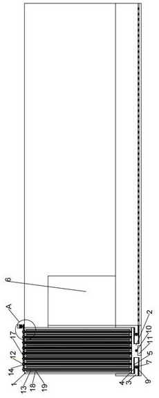
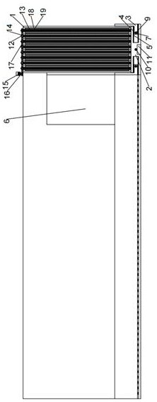
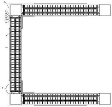
[0027] Such as Figure 1-3 As shown, several of the concave connection wall panels 1 are connected together through a replaceable connection structure, and several of the I-shaped support blocks 2 are equipped with an adjustment connection structure, and several of the concave connection wall panels 1 are connected through the adjustment The connection structure is connected to the plurality of I-shaped support blocks 2;
[0028] Specifically, the adjustment connection structure includes: several L-shaped extrusion fixing plates 3, several limit telescopic sliders 4, several limit telescopic slideways 5, several L-shaped side wall connecting plates 6, several A magnetic limit tube 7, several side wall sealing plates 8, a magnetic limit assembly and an auxiliary vibration assembly;
[0029] Concretely, several said limiting telescopic slides 5 are evenly installed on the inner side of several said I-shaped support blocks 2 respectively, and several said limiting telescopic sli...
Embodiment 2
[0032] Such as Figure 1-3 As shown, the magnetic limit assembly includes: a pair of negative electromagnet rods 9, a positive electromagnet rod 10 and a pair of batteries 11;
[0033] Specifically, a pair of negative electromagnet rods 9 are respectively movably inserted on the inside of a pair of magnetic limit tubes 7 on the L-shaped extruded fixed plate 3, and the positive electromagnet rod 10 is movably inserted in the working On the inside of the magnetic limit tube 7 on the type support block 2, a pair of said accumulators 11 are movably inserted on a pair of said negative pole electromagnet rods 9 and said positive pole electromagnet rods 10 respectively.
[0034] During use, a pair of negative pole electromagnet rods 9 and positive pole electromagnet rods 10 are energized by a pair of storage batteries 11, and a pair of L-shaped extruding fixed plates are pressed in 3 directions by the magnetic adsorption of a pair of negative pole electromagnet rods 9 and positive po...
Embodiment 3
[0036] Such as Figure 1-3 As shown, the auxiliary vibration assembly includes: several vibration shafts 12, several rotating sector pieces 13, several rotating concave wheels 14, a vibration driver 15, a rotating driving concave wheel 16 and a vibration belt 17;
[0037]Specifically, several rotating sector pieces 13 are evenly mounted on several vibration shafts 12, the rotating concave wheels 14 are mounted on several vibration shafts 12, and the rotating driving concave wheels 16 are mounted on On the driving end of the vibration driver 15 , the vibration belt 17 is sleeved on the rotary driving concave wheel 16 and the rotary concave wheel 14 .
[0038] When in use, first insert several vibrating shafts 12 into the inner sides of several supporting limit tubes 22, run through the vibrating driver 15, drive the rotation on the driving end of the vibrating driver 15 to drive the concave wheel 16 to rotate, and drive the concave wheel by rotating 16 drives the vibrating bel...
PUM
 Abstract
Description
Claims
Application Information
 - R&D
- Intellectual Property
- Life Sciences
- Materials
- Tech Scout
- Unparalleled Data Quality
- Higher Quality Content
- 60% Fewer Hallucinations
Browse by: Latest US Patents, China's latest patents, Technical Efficacy Thesaurus, Application Domain, Technology Topic, Popular Technical Reports.
© 2025 PatSnap. All rights reserved.Legal|Privacy policy|Modern Slavery Act Transparency Statement|Sitemap|About US| Contact US: help@patsnap.com


