Control device for automatically adjusting laser incident angle and using method thereof

A laser incident angle and automatic adjustment technology, applied in the field of laser measurement, can solve problems such as inability to compensate, exceed the receiving range, and poor incident light angle, so as to achieve good applicability and easy shock absorption.

Pending Publication Date: 2022-02-18
桂林欧瑞德科技有限责任公司
View PDF10 Cites 3 Cited by
  • Summary
  • Abstract
  • Description
  • Claims
  • Application Information

AI Technical Summary

Problems solved by technology

[0003] The measurement principle of the laser probe is usually the triangulation method, which requires the sensor to face the product. In the scanning of complex parts, such as blades and screws, the angle of incident light is often not good, and the angle of reflected light exceeds the receiving range. The current technology is only the rotation of the Z axis to compensate the incident angle of the laser, but the incident angle caused by the tilt of the product is out of range. This technology cannot compensate. It needs a space steering gyroscope structure to solve it, which is very troublesome.

Method used


Image

  • Control device for automatically adjusting laser incident angle and using method thereof
  • Control device for automatically adjusting laser incident angle and using method thereof
  • Control device for automatically adjusting laser incident angle and using method thereof

Examples


Embodiment 1

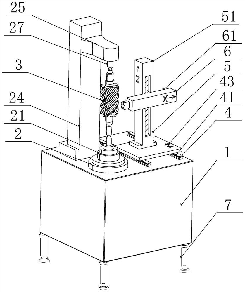
[0032] Such as figure 1 As shown, the present invention is a control device for automatically adjusting the incident angle of laser light and its use method, which includes a working box 1, and one end of the top of the working box 1 is provided with a clamping mechanism 2, which is convenient for clamping the workpiece 3, and the working box 1 is close to the clamping mechanism 2 The top of one end is equipped with a Y-axis moving mechanism 4, the top of the Y-axis moving mechanism 4 is equipped with a Z-axis moving mechanism 5, and one end of the outer wall of the Z-axis moving mechanism 5 is equipped with an X-axis moving mechanism 6. Through each axial moving mechanism, it is convenient to move the laser The position of the ranging sensor 64 and the dead corner at the bottom of the working box 1 are provided with a shock absorbing mechanism 7 to reduce the vibration of the device and facilitate the adjustment of the height of the working box 1 so that it remains horizontal....

Embodiment 2

[0035] see Figure 1-2 , further improvements have been made on the basis of Example 1:

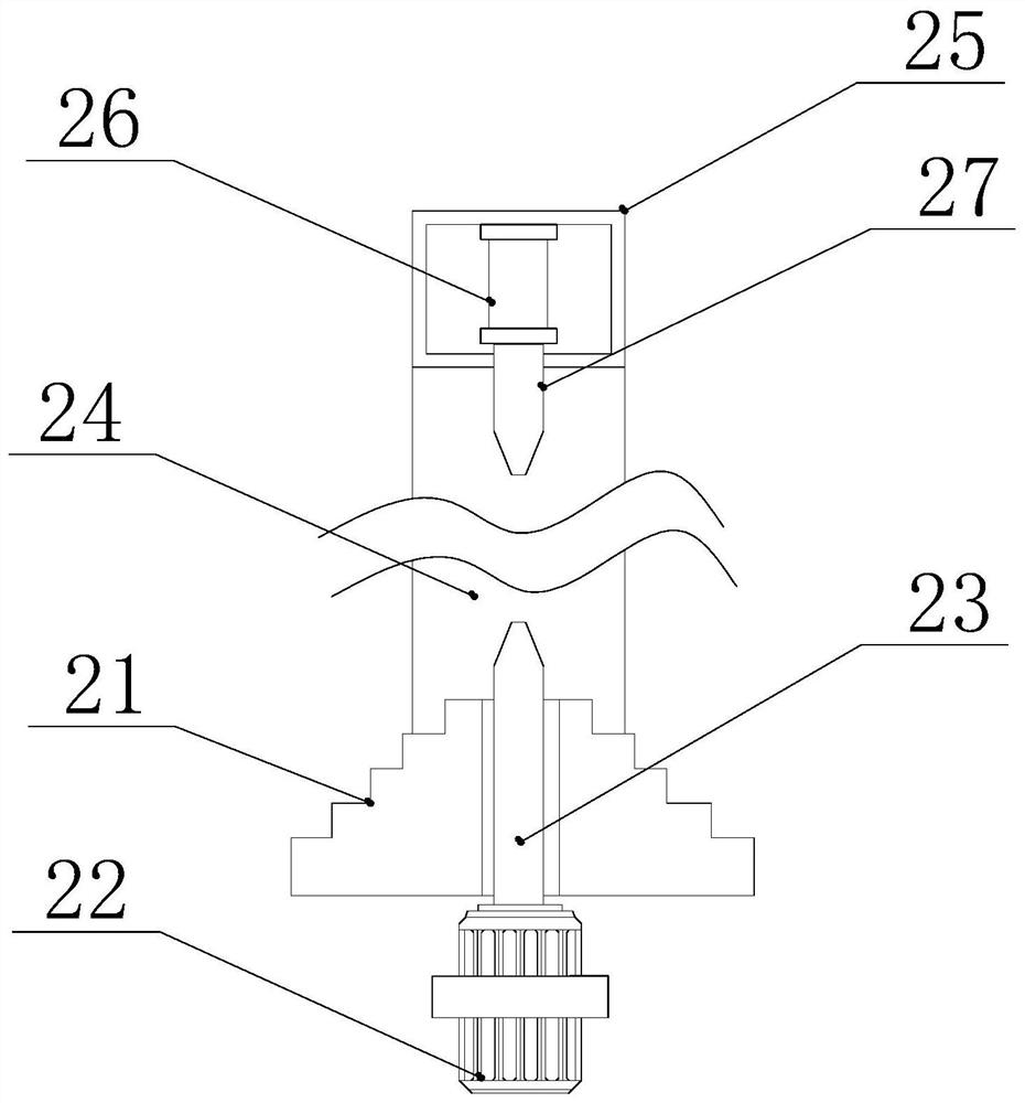
[0036] In order to quickly fix the workpiece 3, the clamping mechanism 2 includes a turntable 21 and a worktable 24. The turntable 21 is fixedly connected to one end of the top end of the outer wall of the work box 1, and the work box 1 is fixedly connected to a first stepper motor 22 at the bottom end of the turntable 21. The stepping motor 22 passes through the turntable 21 and is fixedly connected with the first ejector rod 23, and the first ejector rod 23 is driven to rotate by the first stepping motor 22, so as to facilitate the rotation of the workpiece 3 and change its angle.

[0037]In this embodiment, in order to adapt to different sizes of workpieces 3, the workbench 24 is fixedly connected to the top of the work box 1 near the end of the turntable 21, and the outer wall of the top block of the workbench 24 near the end of the turntable 21 is fixedly connected with a horizontal ...

Embodiment 3

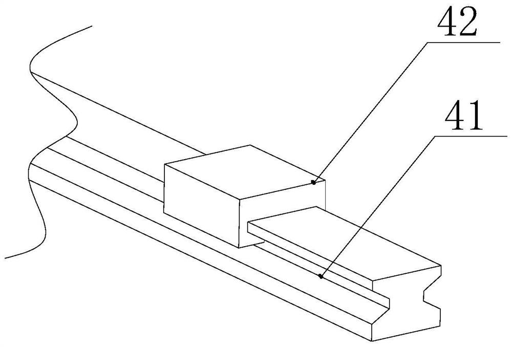
[0039] see figure 1 , image 3 , Figure 4 and Figure 5 , further improvements have been made on the basis of Example 1:

[0040] In order to move the laser ranging sensor 64 of the adjustment device along the Y axis, the Y axis moving mechanism 4 includes two rails 41, the two rails 41 are screwed on the top of the working box 1, and the two rails 41 are respectively slidingly connected with linear motors 42 , the number of linear motors 42 is four, and the four linear motors 42 are evenly distributed on the two rails 41, and the tops of the four linear motors 42 are fixedly connected to the bottom of the moving block 43, and the movement of the linear motors 42 is convenient to drive the laser distance sensor 64 moves, and at the same time can accurately control the position of its movement.

[0041] In this embodiment, in order to adjust the movement of the laser ranging sensor 64 along the Z axis, the Z axis moving mechanism 5 includes a vertical arm 51, the vertical ...


PUM


Abstract

The invention discloses a control device for automatically adjusting a laser incident angle and a using method thereof. The device comprises a working box, a clamping mechanism is arranged at one end of the top of the working box, a Y-axis moving mechanism is arranged at the top of the end, close to the clamping mechanism, of the working box, a Z-axis moving mechanism is arranged at the top of the Y-axis moving mechanism, and an X-axis moving mechanism is arranged at one end of the outer wall of the Z-axis moving mechanism. Damping mechanisms are arranged at the dead corners of the bottom of the working box. The Y-axis moving mechanism comprises a moving block. The Z-axis moving mechanism comprises a movable block. The beneficial effects of the control device are that a product is actively adjusted to face a laser head through rotation of a rotary table according to the shape change of the product, and self-adaptive measurement of the laser incident angle can be realized; a linear motor drives the moving block to move, a second stepping motor drives the movable block to move, and a second electric push rod drives an extension rod to move, so that the position of a laser distance measuring sensor is conveniently adjusted; and a hydraulic cylinder drives a hydraulic rod to move to facilitate damping of the device, meanwhile, the overall length can be changed, and the device can be kept horizontal.

Description

technical field [0001] The invention relates to the technical field of laser measurement, in particular to a control device for automatically adjusting a laser incident angle and a method for using the same. Background technique [0002] Laser measurement technology has been commercialized, samples have been made, a lot of experience has been accumulated, and many practical problems have been solved. It has a good market prospect. This technology has universal adaptability, especially for products with large curvature changes. Applicability makes the application of laser scanning technology more automatic and intelligent. [0003] The measurement principle of the laser probe is usually the triangulation method, which requires the sensor to face the product. In the scanning of complex parts, such as blades and screws, the angle of incident light is often not good, and the angle of reflected light exceeds the receiving range. The current technology is only the rotation of the...

Claims


Application Information

Patent Timeline
Patent Type & Authority Applications(China)
IPC IPC(8): G01B11/24G01B11/14
CPCG01B11/24G01B11/14
Inventor 张志成李艳
Owner 桂林欧瑞德科技有限责任公司
Why Eureka
Try Eureka