Vertical circuit breaker and high-voltage switchgear using vertical circuit breaker

A circuit breaker, vertical technology, applied in high-voltage/high-current switches, high-voltage air circuit breakers, electrical switches, etc., can solve the problem of high development cost, and achieve the effect of low research and development cost, convenient layout and height reduction

Pending Publication Date: 2022-02-18
PINGGAO GRP +3
View PDF0 Cites 0 Cited by
  • Summary
  • Abstract
  • Description
  • Claims
  • Application Information

AI Technical Summary

Problems solved by technology

[0005] The purpose of the present invention is to provide a vertical circuit breaker to solve the technical problem in the prior art that the arc extinguishing chamber needs to be redesigned in order to adapt to different wiring modes, resulting in high development costs; High-voltage switchgear for circuit breakers to solve the above-mentioned technical problems

Method used


Image

  • Vertical circuit breaker and high-voltage switchgear using vertical circuit breaker
  • Vertical circuit breaker and high-voltage switchgear using vertical circuit breaker
  • Vertical circuit breaker and high-voltage switchgear using vertical circuit breaker

Examples


specific Embodiment 1

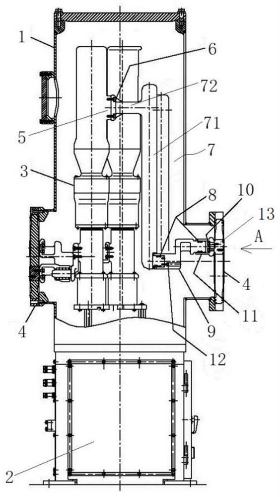
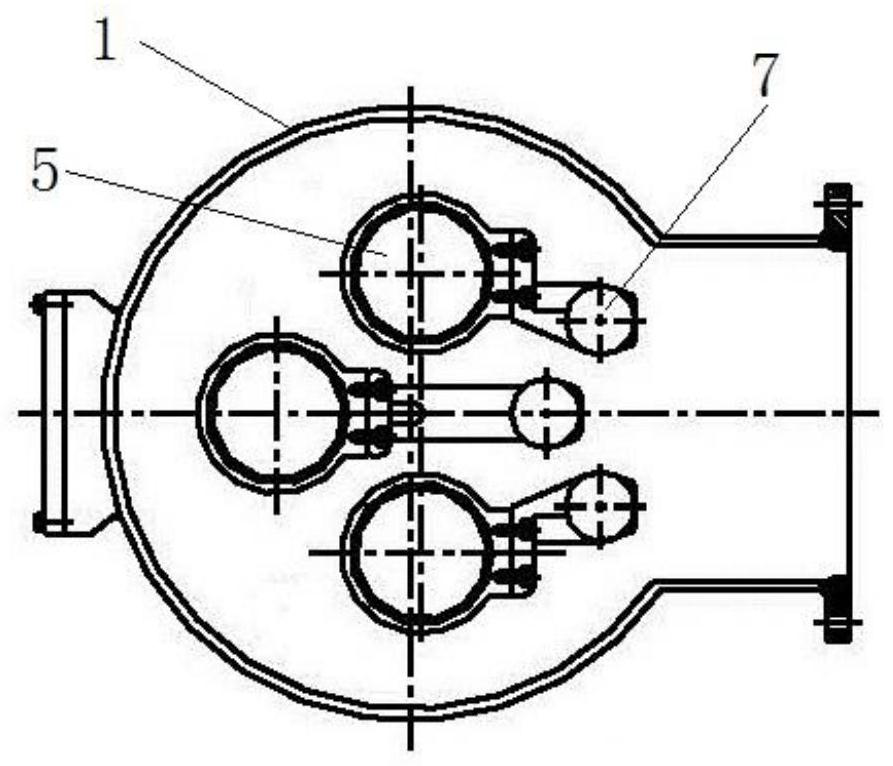
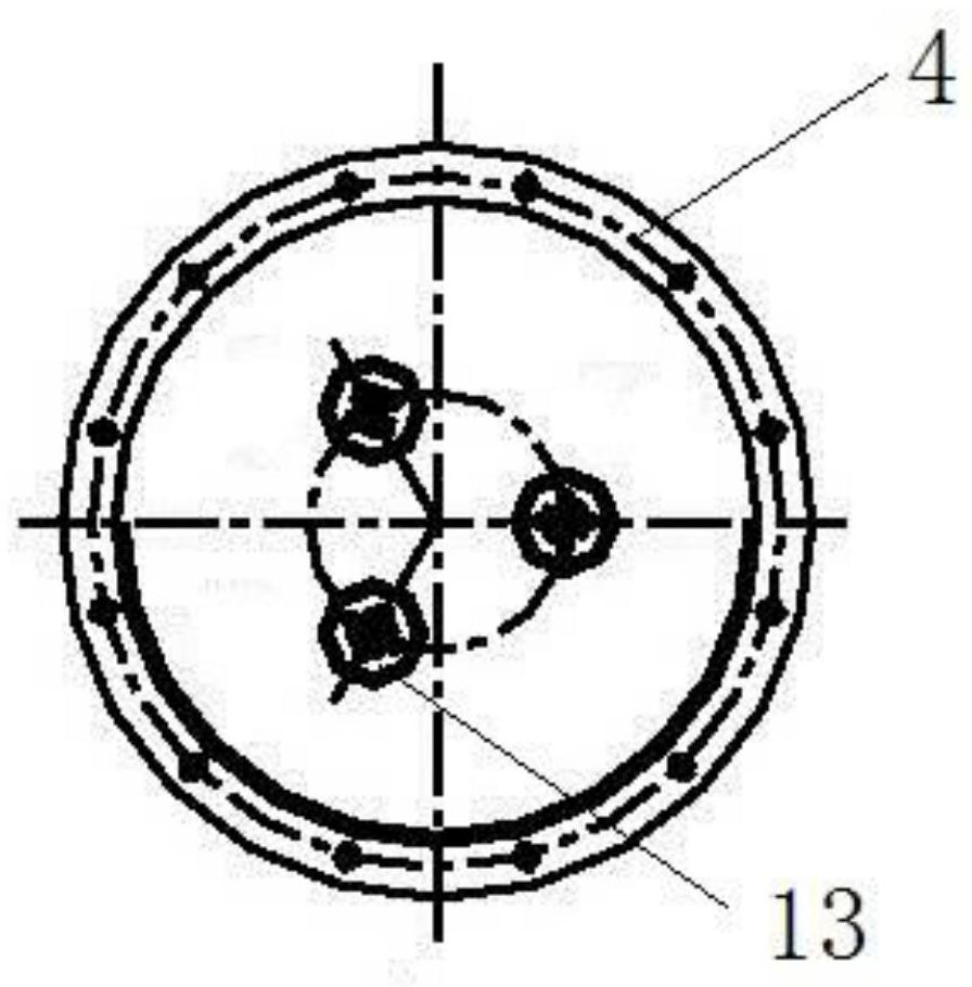
[0087] Such as Figure 1 to Figure 11 As shown, the vertical circuit breaker in this embodiment is a three-phase common box type circuit breaker. The vertical circuit breaker includes a housing 1, and a three-phase arc extinguishing chamber 3 is arranged in the housing 1. The housing 1 and the arc extinguishing chamber 3 are arranged up and down. Extending, the arc extinguishing chamber 3 includes a moving end at the bottom and a static end at the top, and an operating mechanism 2 capable of driving the moving end to move up and down is installed on the outside of the housing 1 . The two sides of the casing 1 are respectively provided with insulators 4, figure 1 The insulator 4 on the left side is used as the outgoing line at the moving end, and the insulator 4 on the right is used as the outgoing line at the static end. The insulator 4 on the right is located below the static end of the arc extinguishing chamber 3, and the static end of the arc extinguishing chamber 3 of eac...

specific Embodiment 2

[0105] Such as Figure 12 and Figure 13 As shown, the difference from Embodiment 1 is that in Embodiment 1, a port structure is arranged on the adjustment conductor. In this embodiment, in the vertical circuit breaker 19, a first port structure 14 and a second port structure 15 are arranged on the adjusting conductor 7, the first port structure 14 corresponds to the first bus bar 20 of the GIS, and the second port structure 15 It corresponds to the second bus 21 of the GIS. When in use, adjust conductors 7 of different lengths are selected according to the heights of the first GIS bus 20 and the second GIS bus 21 , and port structures are provided at corresponding positions of the adjust conductors 7 .

Embodiment 1

[0107] In Embodiment 1, by arranging the first connection part and the second connection part of the lead-out conductor in an offset position, the position of the second connection part can be adjusted while rotating the lead-out conductor. In this embodiment, the lead-out conductor has a straight rod structure, that is, the first connecting portion and the second connecting portion are located on the same straight line. At this time, no matter how the lead-out conductor is rotated, the circumferential position of the second connecting portion will not change. When the position of the second connecting part does not need to be changed, the vertical circuit breaker in the present invention can be a three-phase box-divided circuit breaker.


PUM


Abstract

The invention relates to a vertical circuit breaker and a high-voltage switchgear using the vertical circuit breaker, and the vertical circuit breaker comprises a shell which extends up and down; an arc extinguish chamber, arranged in the shell and comprising a lower movable end and an upper static end; and an operating mechanism, driving the movable end to move up and down. The shell is provided with a static end insulator, the static end insulator is used for being connected with a bus, the static end insulator is located below the static end, and the static end insulator is provided with an insulator conductor; the vertical circuit breaker further comprises an adjusting conductor, the upper end of the adjusting conductor being connected with the static end, and the lower end of the adjusting conductor extending downwards to a position corresponding to the insulator conductor; and a lead-out conductor, connected with the adjusting conductor and the insulator conductor. The position of the insulator conductor in the vertical direction is adaptively changed according to different wiring modes, the wiring requirement can be met only by selecting the leading-out conductors with different lengths, the structure of the arc extinguish chamber does not need to be changed, the arc extinguish chamber does not need to be redesigned, researched and developed, and the research and development cost is low.

Description

technical field [0001] The invention relates to a vertical circuit breaker and high-voltage switchgear using the vertical circuit breaker. Background technique [0002] The vertical circuit breaker is composed of an arc extinguishing chamber, a casing and an operating mechanism, and the casing is filled with SF with a certain operating pressure. 6 The gas and arc extinguishing chamber are located in the housing, both of which extend up and down, the moving end of the arc extinguishing chamber is on the bottom, and the static end is on the top, and the operating mechanism drives the moving end to move up and down. The casing is provided with a static end wire outlet and a moving end wire outlet. The static end wire outlet is horizontally corresponding to the static end to lead out the static end, and the moving end wire outlet is horizontally corresponding to the moving end to lead out the moving end. When in use, a static end insulator is installed on the outlet of the stat...

Claims


Application Information

Patent Timeline
IPC IPC(8): H01H33/02H01H33/04H01H33/53
CPCH01H33/04H01H33/53H01H33/02
Inventor 吕进张克选秦晓宇李要锋朱承治张煜烽勾国营丁鹏翔赵晓雯杨春月吕寻浩张涛锋陈东李松磊李付永孙龙勇姚灿江
Owner PINGGAO GRP
Why Eureka
Try Eureka