
Fault diagnosis method and device for distributed photovoltaic power generation system, and electronic equipment

A fault diagnosis device and distributed photovoltaic technology, applied in the monitoring of photovoltaic systems, photovoltaic power generation, circuit devices, etc., can solve the problems that faults cannot be eliminated in time, affect power generation efficiency, hot spots, etc., so as to avoid the impact of power generation efficiency. Effect

Pending Publication Date: 2022-02-18
BEIJING CHINA POWER INFORMATION TECH
View PDF3 Cites 0 Cited by
  • Summary
  • Abstract
  • Description
  • Claims
  • Application Information

AI Technical Summary

Problems solved by technology

Long-term shading will also cause hot spots on the components to damage the photovoltaic components
[0006] It is one of the common problems in the operation of distributed photovoltaic power plants to cause a significant drop in power generation efficiency due to the blocking of photovoltaic panels. Foreign objects such as weeds, dust, rain, and snow are blocked by foreign objects, and it is difficult for operation and maintenance personnel to detect them without going to the site; or the panels are covered by buildings. Objects, tree shade, and battery components with unreasonable row spacing are shaded by objects, and the shaded area will change with the angle of the sun. As a result, even if the operation and maintenance personnel are on site, they may not be able to be found in time.
In view of the fact that the distributed photovoltaic power generation system itself has many points and wide areas and it is difficult to detect faults in time, the faults cannot be eliminated in time, which affects its power generation efficiency

Method used


Image

  • Fault diagnosis method and device for distributed photovoltaic power generation system, and electronic equipment
  • Fault diagnosis method and device for distributed photovoltaic power generation system, and electronic equipment
  • Fault diagnosis method and device for distributed photovoltaic power generation system, and electronic equipment

Examples


Embodiment 1

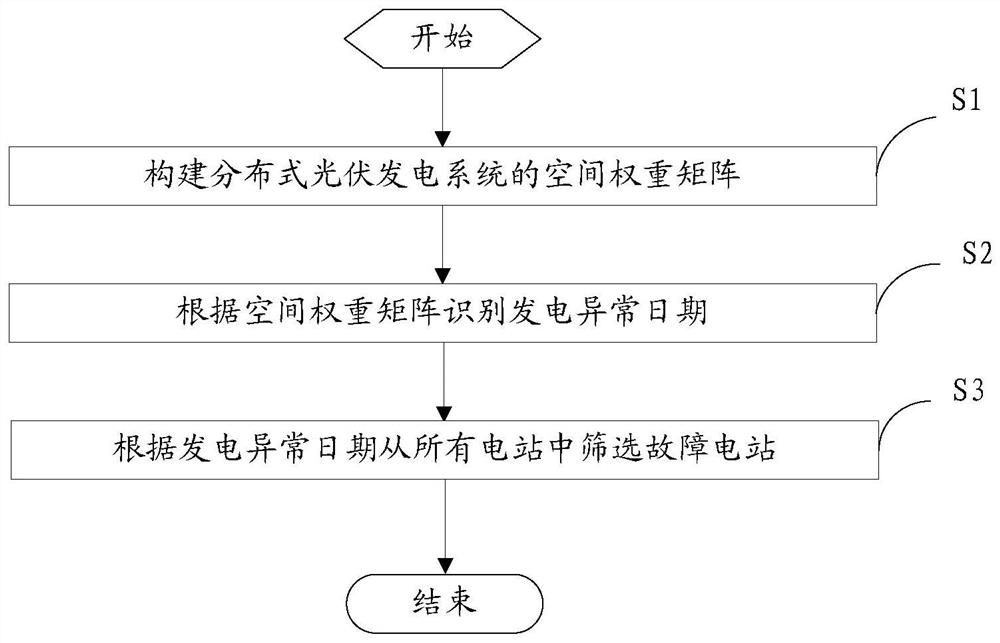
[0052] figure 1 It is a flowchart of a fault diagnosis method for a distributed photovoltaic power generation system according to an embodiment of the present application.

[0053] Such as figure 1 As shown, the fault diagnosis method provided in this embodiment is applied to corresponding electronic equipment, which can be understood as a computer or server with data calculation and information processing capabilities, which is generally a central control station installed in a distributed photovoltaic power generation system Or the computer or server of the centralized control station. The fault diagnosis method specifically includes the following steps:

[0054] S1. Construct the spatial weight matrix of the distributed photovoltaic power generation system.

[0055] That is, a spatial weight matrix of all power stations including the distributed photovoltaic power generation system is constructed, and each element of the matrix corresponds to a weight coefficient of a po...

Embodiment 2

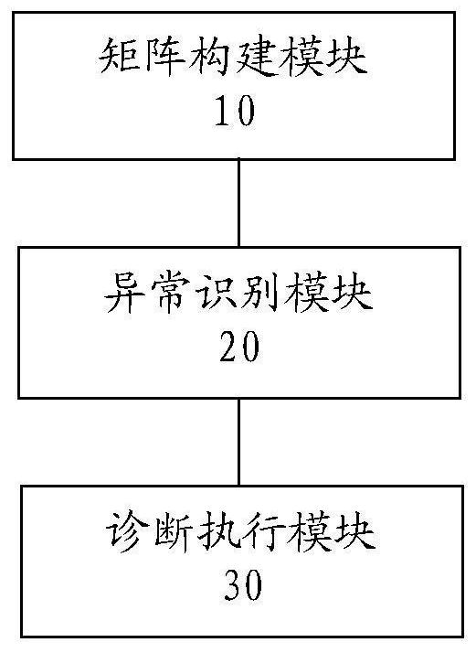
[0075] figure 2 It is a block diagram of a fault diagnosis device for a distributed photovoltaic power generation system according to an embodiment of the present application.

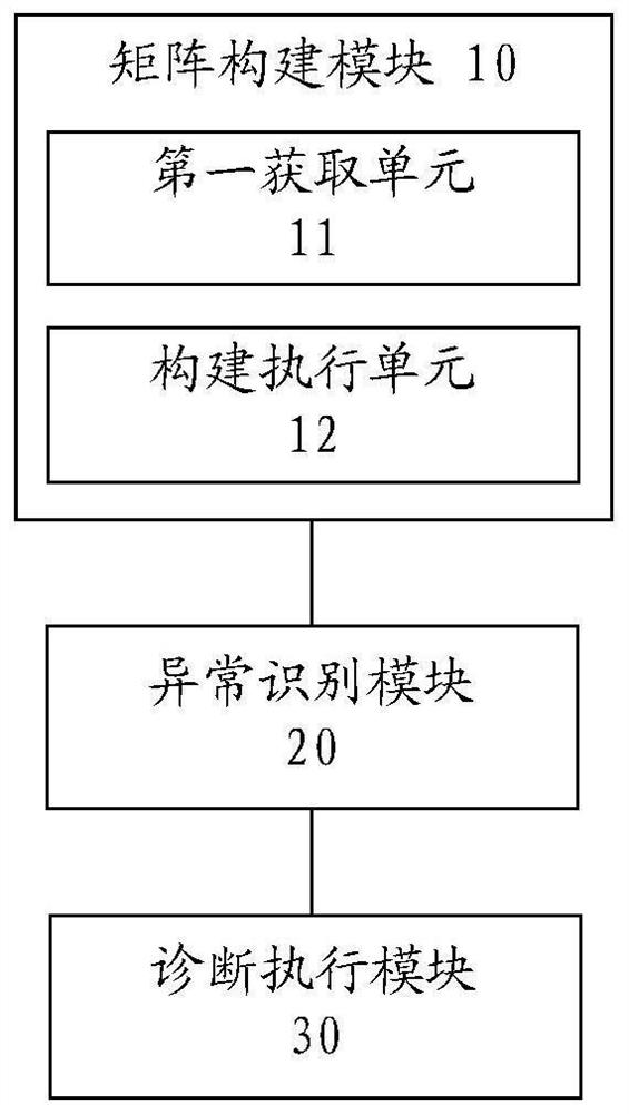
[0076] Such as figure 2 As shown, the fault diagnosis device provided in this embodiment is applied to corresponding electronic equipment, which can be understood as a computer or server with data calculation and information processing capabilities, which is generally a central control station installed in a distributed photovoltaic power generation system Or the computer or server of the centralized control station. The fault diagnosis device specifically includes a matrix construction module 10 , an abnormality identification module 20 and a diagnosis execution module 30 .

[0077] The matrix building block is used to construct the spatial weight matrix of the distributed photovoltaic power generation system.

[0078] That is, a spatial weight matrix of all power stations including the distribut...

Embodiment 3

[0098] This embodiment provides an electronic device, which can be understood as a computer or server with data calculation and information processing capabilities, which is generally a computer or server installed in the central control station or centralized control station of a distributed photovoltaic power generation system , and is provided with the fault diagnosis device of the previous embodiment.

[0099] The fault diagnosis device is specifically used to construct the spatial weight matrix of all power stations in the distributed photovoltaic power generation system. Each element of the spatial weight matrix corresponds to the weight coefficient of a power station; Faulty plants are identified from all of the above plants. In this way, the faulty power station can be identified without on-site inspection, and the operation and maintenance personnel can eliminate the fault in time, thereby avoiding the impact on the power generation efficiency of the distributed photo...


PUM


Abstract

The invention discloses a fault diagnosis method and device for a distributed photovoltaic power generation system, and electronic equipment. The method specifically comprises the following steps: constructing a space weight matrix of all power stations in the distributed photovoltaic power generation system, and enabling each element of the space weight matrix to correspond to a weight coefficient of one power station; generating abnormal dates of all power stations are obtained according to the spatial weight matrix; and identifying a fault power station from all the power stations according to the abnormal power generation date. In this way, the fault power station can be identified without on-site inspection, and operation and maintenance personnel can eliminate the fault in time, so that the power generation efficiency of the distributed photovoltaic power generation system is prevented from being affected.

Description

technical field [0001] The present application relates to the field of photovoltaic technology, and more specifically, to a fault diagnosis method and device for a distributed photovoltaic power generation system. Background technique [0002] With the large-scale development and utilization of new energy in the domestic market, the photovoltaic industry has gradually matured. With the deepening implementation of the State Council's energy-saving and emission reduction policies to promote photovoltaic development, it will still maintain a high-speed growth trend. However, due to the small scale of distributed photovoltaic power plants, remote and scattered locations, and complex and diverse distribution terrains, the photovoltaic power plant management system currently on the market lacks intelligent operation and maintenance methods, resulting in many problems during the operation of the power plant. [0003] Distributed photovoltaic power generation system, also known as ...

Claims


Application Information

Patent Timeline
Patent Type & Authority Applications(China)
IPC IPC(8): H02S50/00H02J3/38G06F17/16G06F17/18
CPCH02S50/00H02J3/381G06F17/16G06F17/18H02J2203/20H02J2300/24Y02E10/56
Inventor 张静袁葆张文陈雁万泉闫富荣周春欧阳红
Owner BEIJING CHINA POWER INFORMATION TECH
Learn More