Garbage incineration coupling boiler system

A waste incineration and boiler technology, applied in the field of boiler systems for waste incineration treatment, can solve problems such as poor economic benefits of power generation, difficult pretreatment, formation of chlorine corrosion, etc.

Active Publication Date: 2021-12-14
TSINGHUA UNIV
View PDF0 Cites 0 Cited by
  • Summary
  • Abstract
  • Description
  • Claims
  • Application Information

AI Technical Summary

Problems solved by technology

But at the same time, its incineration treatment also has some difficulties: the degree of garbage classification is poor, the pretreatment is difficult, and it is difficult to evenly feed materials to participate in the furnace combustion; the calorific value of garbage is low, and the economic benefits of power generation are poor; the products of garbage incineration will form chlorine corrosion in the boiler, It may lead to safety accidents such as tube explosions on the heating surface of the boiler, which will cause huge loss of personnel and property; waste incineration is likely to produce dioxins, which are very toxic and bioaccumulative, causing environmental pollution problem cannot be ignored
[0003] Most of the solution ideas are to solve the above problems by designing special waste incineration devices, but it is necessary to install supporting flue gas treatment devices, and the low calorific value of waste is directly used for power generation and the economic benefits are poor.
There is also a small amount of waste incineration using circulating flow annular bed boilers, but it is required to carry out good crushing pretreatment before the waste is put into the furnace. Some waste contains bricks, glass, metal and other non-combustible materials, which are difficult to fluidize, and the bottom slag is difficult to treat.

Method used


Image

  • Garbage incineration coupling boiler system

Examples


Embodiment Construction

[0027] Embodiments of the present invention are described in detail below, examples of which are shown in the drawings, wherein the same or similar reference numerals designate the same or similar elements or elements having the same or similar functions throughout. The embodiments described below by referring to the figures are exemplary only for explaining the present invention and should not be construed as limiting the present invention.

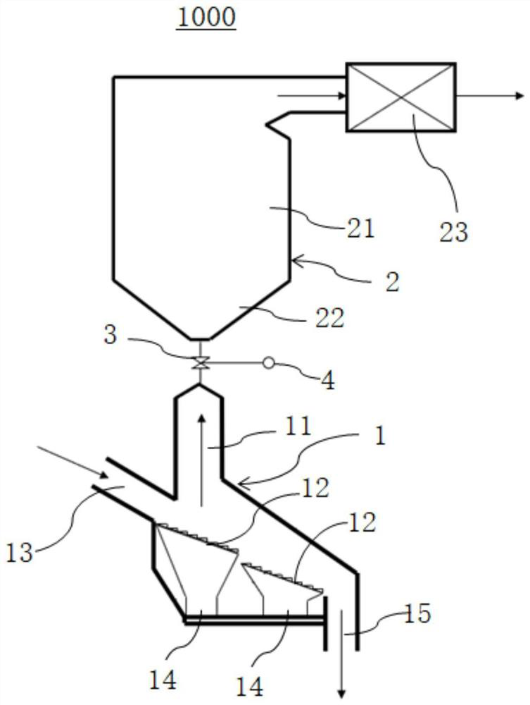
[0028] Combine below figure 1 The waste incineration coupled boiler system 1000 according to the embodiment of the present invention will be described.

[0029] Such as figure 1 As shown, a waste incineration coupled boiler system 1000 according to an embodiment of the present invention includes a waste incineration bed combustion combustion device 1 and a suspension combustion device 2 . Among them, the waste incineration layer combustion device 1 has a flue gas outlet 11, and the waste incineration layer combustion device 1 is used f...


PUM


Abstract

The invention discloses a garbage incineration coupled boiler system, which includes a garbage incineration layer combustion device and a suspension combustion device. The garbage incineration layer combustion device has a flue gas outlet, and the garbage incineration layer combustion device is used for layer combustion of garbage; The suspension combustion device is equipped with a cold ash hopper and an exhaust gas treatment unit connected to the furnace. A connecting valve is set between the cold ash hopper and the flue gas outlet. The coal-fired flue gas is mixed and burned, and the tail gas treatment unit is used to treat the tail gas generated by the suspension combustion device and the waste incineration layer combustion device. The invention can simply and efficiently utilize the heat of garbage incineration and can solve the flue gas pollutants produced by garbage incineration, while improving the economic benefits of the power plant and better assuming social responsibility.

Description

technical field [0001] The invention relates to the technical field of boiler systems for waste incineration treatment, in particular to a waste incineration coupled boiler system. Background technique [0002] Garbage incineration is currently a relatively common way of urban waste treatment. Because it can use garbage as energy and has good characteristics of volume reduction and volume reduction, it has attracted widespread attention and attention, and has become the main way of waste treatment. But at the same time, its incineration treatment also has some difficulties: the degree of garbage classification is poor, the pretreatment is difficult, and it is difficult to evenly feed materials to participate in the furnace combustion; the calorific value of garbage is low, and the economic benefits of power generation are poor; the products of garbage incineration will form chlorine corrosion in the boiler, It may lead to safety accidents such as tube explosions on the heati...

Claims


Application Information

Patent Timeline
Patent Type & Authority Patents(China)
IPC IPC(8): F23G5/16F23G5/44F23J1/00F23C10/18
CPCF23G5/165F23G5/444F23J1/00F23C10/18F23G2202/103
Inventor 蒋苓张缦杨海瑞吕俊复
Owner TSINGHUA UNIV
Why Eureka
Try Eureka