Polarization visual chart projector

A technology for eye charts and projectors, applied in instruments, comprehensive refractometers, medical science, etc., can solve problems such as poor craftsmanship, difficult manufacturing, and high manufacturing costs

Pending Publication Date: 2022-02-22
株式会社湖碧驰
View PDF1 Cites 1 Cited by
  • Summary
  • Abstract
  • Description
  • Claims
  • Application Information

AI Technical Summary

Problems solved by technology

[0005] However, because the above-mentioned polarizing film 20 for linearly polarized LCDs in units of lines is not only expensive to manufacture and difficult to manufacture, but also has the problem that process defects are prone to occur when the manufactured polarizing film 20 is attached to the image display device 10

Method used


Image

  • Polarization visual chart projector
  • Polarization visual chart projector
  • Polarization visual chart projector

Examples


Embodiment Construction

[0019] The present invention will be described in detail below with reference to the accompanying drawings. In the drawings, elements performing the same or similar functions as conventional ones are given the same reference numerals.

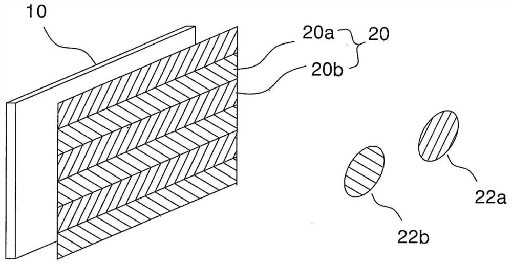
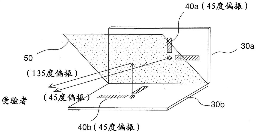
[0020] figure 2 It is a figure which shows the structure of the polarization eye chart projector which concerns on one Example of this invention. Such as figure 2 As shown, the polarized eye chart projector of the present invention includes a first image display device 30 a , a second image display device 30 b and a beam splitter 50 .

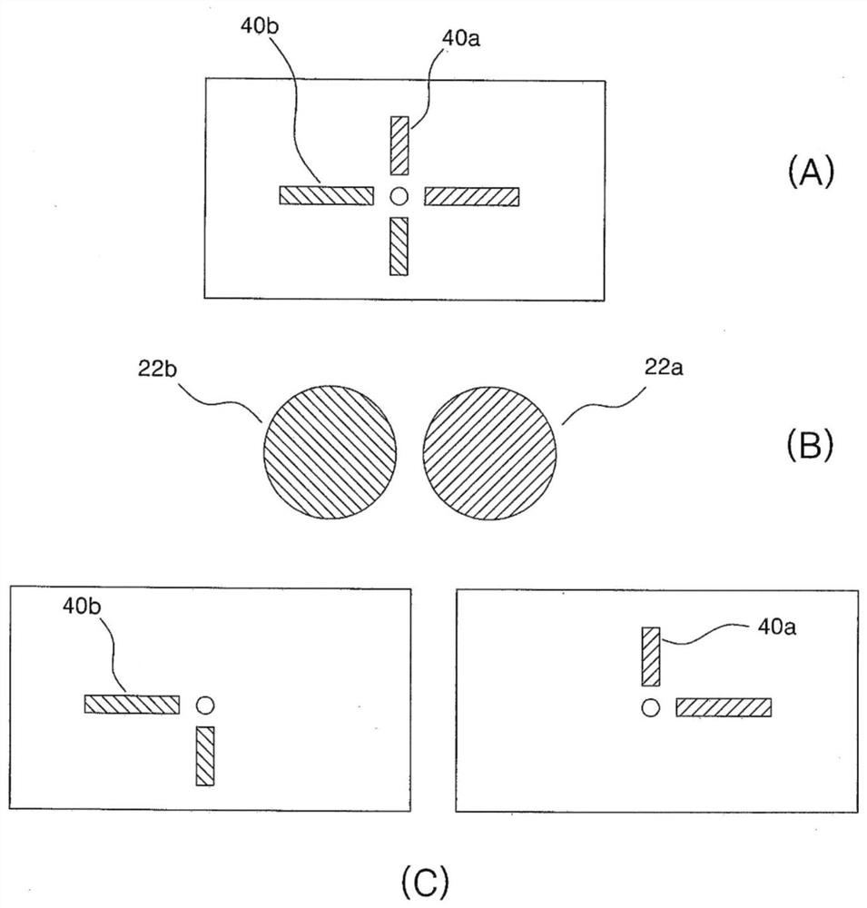
[0021] The first image display device 30a projects a first eye chart 40a polarized in a first direction, and the second image display device 30b projects a second eye chart 40b polarized in a second direction. The beam splitter 50 makes the first eye chart 40a emitted from the first image display device 30a directly pass through, projects the first eye chart 40a polarized in the first direction toward the s...


PUM


Abstract

Disclosed is a polarized visual chart projector that generates visual charts polarized differently from each other in order to perform binocular visual inspection. The polarized visual chart projector includes: a first image display device (30a) that projects a first visual chart (40a) polarized in a first direction; a second image display device (30b) that projects a second visual chart (40b) polarized in a second direction; and a beam splitter (50) that directly passes through the first visual chart (40a) emitted from the first image display device (30a), projects the first visual chart (40a) polarized in the first direction toward the subject, and reflects the second visual chart (40b) polarized in the second direction emitted from the second image display device (30b), so that the second visual chart (40c) polarized in a third direction different from the first direction is projected in the direction of the subject.

Description

technical field [0001] The present invention relates to a polarized eye chart projector, and more particularly, to a polarized eye chart projector for generating eye charts polarized differently for binocular vision examination. Background technique [0002] Binocular vision is a term corresponding to monocular vision, and refers to a method of recognizing objects respectively recognized by both eyeballs as one object with the assistance of both eyeballs when looking at the same position of an object with both eyes. Even if you look at the same object, the left and right eyes will see a slightly different image due to the position difference of about 6cm. This is called binocular parallax. Despite this parallax, often we see objects as images fused into one rather than as if overlapping, this is known as binocular fusion. That is, when objects with similar shapes are displayed to the right eye and left eye, the human brain recognizes that there is one object by fusing the i...

Claims


Application Information

Patent Timeline
Patent Type & Authority Applications(China)
IPC IPC(8): A61B3/00A61B3/032G03B21/00G03B21/20
CPCA61B3/0041A61B3/032G03B21/006G03B21/2073A61B3/028A61B3/08G02B30/25
Inventor 赵珉秀
Owner 株式会社湖碧驰
Why Eureka
Try Eureka