
Insulator cleaning machine and insulator cleaning method

A technology for insulators and machines, applied in the field of insulator cleaning machines and insulator cleaning, which can solve the problems of low flexibility, inconvenient real-time adjustment of nozzle position, insulator cleaning devices that cannot be fully applied to high-voltage converter stations, etc.

Active Publication Date: 2022-02-22
DALI BUREAU OF ULTRA HIGH VOLTAGE TRANSMISSION CO CHINA SOUTHERN POWER GRID CO LTD
View PDF15 Cites 1 Cited by
  • Summary
  • Abstract
  • Description
  • Claims
  • Application Information

AI Technical Summary

Problems solved by technology

Usually, the surface of insulators is cleaned by high-pressure jet water jets. Traditional insulator cleaning devices cannot be fully applied to high-voltage converter stations and cleaning of high-distance insulator strings.
In the traditional insulator cleaning device, the nozzle is set on the working platform of the lift scissors, and the nozzle is operated on the working platform to clean the insulator. The overall structure is relatively complicated, the flexibility is not high, and the positioning operation of the nozzle is difficult. Adjust the nozzle position

Method used


Image

  • Insulator cleaning machine and insulator cleaning method
  • Insulator cleaning machine and insulator cleaning method
  • Insulator cleaning machine and insulator cleaning method

Examples


Embodiment Construction

[0032] In order to make the above objects, features and advantages of the present invention more comprehensible, specific implementations of the present invention will be described in detail below in conjunction with the accompanying drawings. In the following description, numerous specific details are set forth in order to provide a thorough understanding of the present invention. However, the present invention can be implemented in many other ways different from those described here, and those skilled in the art can make similar improvements without departing from the connotation of the present invention, so the present invention is not limited by the specific embodiments disclosed below.

[0033] In describing the present invention, it should be understood that the terms "center", "longitudinal", "transverse", "length", "width", "thickness", "upper", "lower", "front", " Back", "Left", "Right", "Vertical", "Horizontal", "Top", "Bottom", "Inner", "Outer", "Clockwise", "Counte...


PUM


Abstract

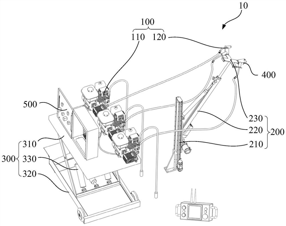
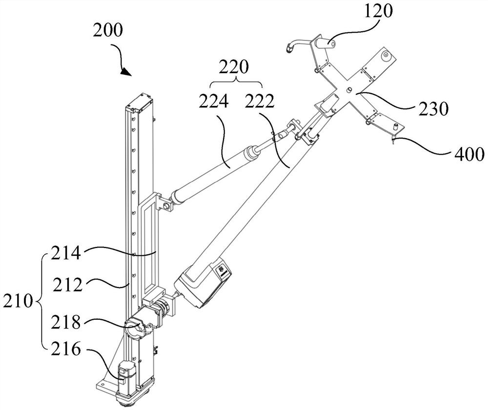
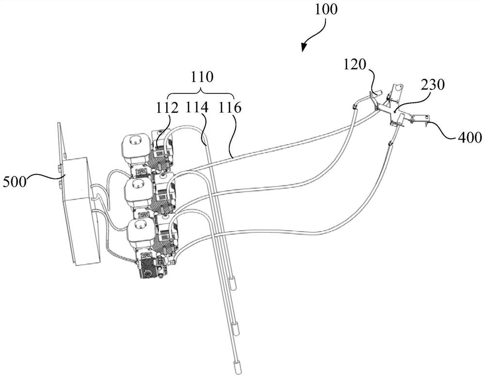
The invention discloses an insulator cleaning machine and an insulator cleaning method. The insulator cleaning machine comprises a waterway adjusting device, a positioning mechanism and a lifting mechanism; the waterway adjusting device comprises a water supply assembly and a spray head; the water supply assembly is used for supplying water to the spray head; the spray head is connected to the positioning mechanism which is used for adjusting the position and orientation of the spray head; the water supply assembly is connected to the lifting mechanism used for adjusting the height of the water supply assembly; the water supply assembly is connected to the lifting mechanism; and the spray head is connected to the positioning mechanism. The water supply assembly is adjusted to the approximate height around an insulator to be cleaned through the lifting mechanism, then the positioning mechanism independently controls the spray head to move; and due to the fact that the spray head is simple in structure, the positioning operation of the positioning mechanism on the spray head is accurate, efficient, high in flexibility and convenient to operate, and the problem that the spray head is difficult to control due to the redundant structure of the waterway adjusting device is avoided. According to the insulator cleaning method, the cleaning of the insulator is realized by independently moving the spray head, and the cleaning effect is good.

Description

technical field [0001] The invention relates to the technical field of electric equipment cleaning, in particular to an insulator cleaning machine and an insulator cleaning method. Background technique [0002] An insulator is a special insulation control that plays an important role in overhead transmission lines. Insulators were mostly used for utility poles in the early years, and gradually developed for high-voltage wire connection towers, mainly for electrical insulation and mechanical fixation. The surface of insulators is usually cleaned by high-pressure jet water jets. Traditional insulator cleaning devices are not fully suitable for high-voltage converter stations and high-distance insulator string cleaning. In the traditional insulator cleaning device, the nozzle is set on the working platform of the lift scissors, and the nozzle is operated on the working platform to clean the insulator. The overall structure is relatively complicated, the flexibility is not high,...

Claims


Application Information

Patent Timeline
Patent Type & Authority Applications(China)
IPC IPC(8): B08B3/02
CPCB08B3/02
Inventor 胡欢杜爱平张义付强赵宏续兴吕禹戴昊辰杨应山余荣兴田松丰郭纯海李强高晗
Owner DALI BUREAU OF ULTRA HIGH VOLTAGE TRANSMISSION CO CHINA SOUTHERN POWER GRID CO LTD
Learn More