Vacuum interferometer device and optical detection method thereof

An optical detection and interferometer technology, applied in the field of optical detection, can solve the problems of large errors, random errors and systematic errors, and low detection accuracy, and achieve the effect of realizing high-precision detection and eliminating random errors and systematic errors

Active Publication Date: 2022-02-22
CHANGCHUN INST OF OPTICS FINE MECHANICS & PHYSICS CHINESE ACAD OF SCI
View PDF5 Cites 0 Cited by
  • Summary
  • Abstract
  • Description
  • Claims
  • Application Information

AI Technical Summary

Problems solved by technology

However, there are defects in the above-mentioned methods: for the detection method in which the interferometer is placed in a normal pressure environment and in front of the glass window, the atmospheric disturbance of the detection arm of the interferometer and the window glass will directly introduce random errors and System error is difficult to remove through high-precision calibration; and for the detection method of placing the collimator and the tested component in the vacuum container at the same time or placing the reference mirror and the tested mirror in the vacuum container, it is necessary to time-sharing Mirror and reference mirror are tested, and then the final result is calculated, so that the final test result is greatly affected by other environmental factors such as vibration, and the detection accuracy is reduced
[0004]Therefore, generally speaking, the current methods for detecting large-aperture optical mirrors and optical systems in a vacuum environment have the disadvantages of complicated operations, large errors, and low detection accuracy. question

Method used


Image

  • Vacuum interferometer device and optical detection method thereof
  • Vacuum interferometer device and optical detection method thereof

Examples


Embodiment Construction

[0029] The following description serves to disclose the present invention to enable those skilled in the art to carry out the present invention. The preferred embodiments described below are only examples, and those skilled in the art can devise other obvious variations. The basic principles of the present invention defined in the following description can be applied to other embodiments, variations, improvements, equivalents and other technical solutions without departing from the spirit and scope of the present invention.

[0030] Those skilled in the art should understand that, in the disclosure of the present invention, the terms "vertical", "transverse", "upper", "lower", "front", "rear", "left", "right", The orientations or positional relationships indicated by "vertical", "horizontal", "top", "bottom", "inner", "outer", etc. are based on the orientation or positional relationship shown in the drawings, which are only for the convenience of describing the present inventi...


PUM

PropertyMeasurementUnit
wavelengthaaaaaaaaaa

Abstract

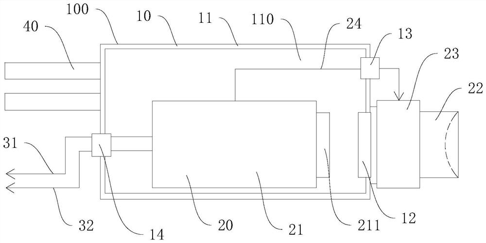
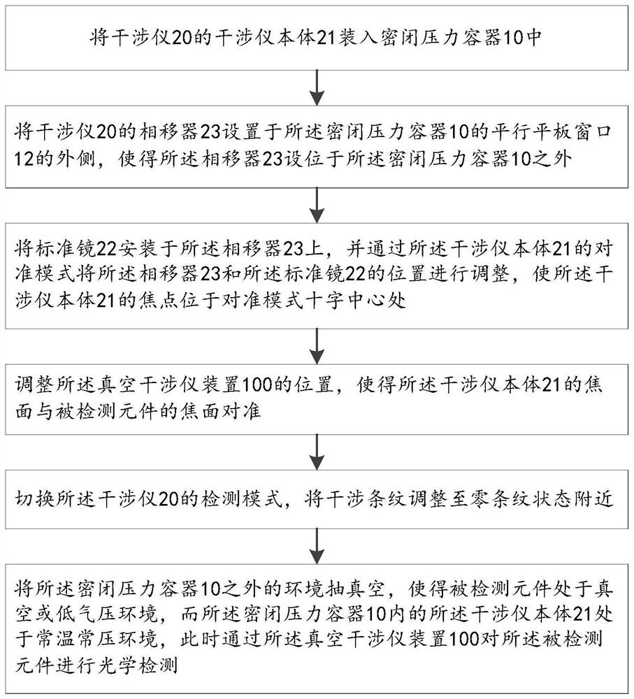
The invention relates to a vacuum interferometer device and an optical detection method thereof. The vacuum interferometer device is characterized in that an interferometer body of an interferometer is separated from a phase shifter and a standard lens, the interferometer body is placed in a normal-temperature and normal-pressure environment, and the phase shifter, the standard lens and a detected element are arranged in a vacuum or low-pressure environment, so that random errors and system errors caused by the parallel flat plate window on an interference detection light path are eliminated, optical detection on the detected element can be realized without atmospheric disturbance, and high-precision detection is realized.

Description

technical field [0001] The invention relates to the technical field of optical detection, in particular to a vacuum interferometer device and an optical detection method thereof. Background technique [0002] Large-aperture optical mirrors and optical systems are generally tested in a laboratory environment. However, as the aperture of the single mirror and the system increases and the focal length becomes longer, the atmospheric disturbance in the laboratory environment will become more obvious, and the impact on optical detection will also increase. On the other hand, EUV (extreme ultraviolet lithography) components or other high-precision components require high detection accuracy. At this time, the existence and disturbance of the atmosphere in the experimental environment will make the detection accuracy unable to meet the requirements. For the detection of large-aperture optical mirrors and optical systems, the current common method is to use interferometers to measure...

Claims


Application Information

Patent Timeline
Patent Type & Authority Applications(China)
IPC IPC(8): G01B11/24G01B9/02056G01B9/02055G01B9/02
CPCG01B11/2441G01B9/02041G01B9/02055G01B9/02056
Inventor 胡海翔罗霄张学军杨茜薛栋林
Owner CHANGCHUN INST OF OPTICS FINE MECHANICS & PHYSICS CHINESE ACAD OF SCI
Why Eureka
Try Eureka