Wind turbine comprising a floating foundation having a plurality of buoyancy bodies

A wind turbine, buoyant body technology, applied in the installation/support of wind turbine configuration, hydrodynamic characteristics/hydrostatic characteristics, floating buildings, etc., can solve problems such as hindering lightweight floating bodies

Pending Publication Date: 2022-02-22
AERODYN CONSULTING SINGAPORE PTE LTD
View PDF6 Cites 0 Cited by
  • Summary
  • Abstract
  • Description
  • Claims
  • Application Information

AI Technical Summary

Problems solved by technology

Thus, the known designs prevent the design of lightweight, material-compatible floating bodies

Method used


Image

  • Wind turbine comprising a floating foundation having a plurality of buoyancy bodies
  • Wind turbine comprising a floating foundation having a plurality of buoyancy bodies
  • Wind turbine comprising a floating foundation having a plurality of buoyancy bodies

Examples


Embodiment Construction

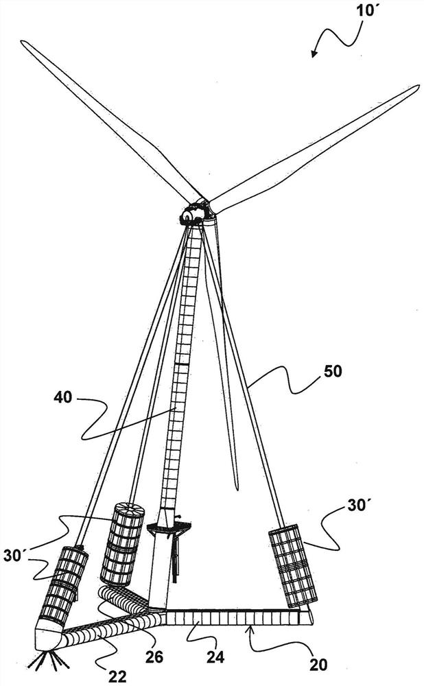
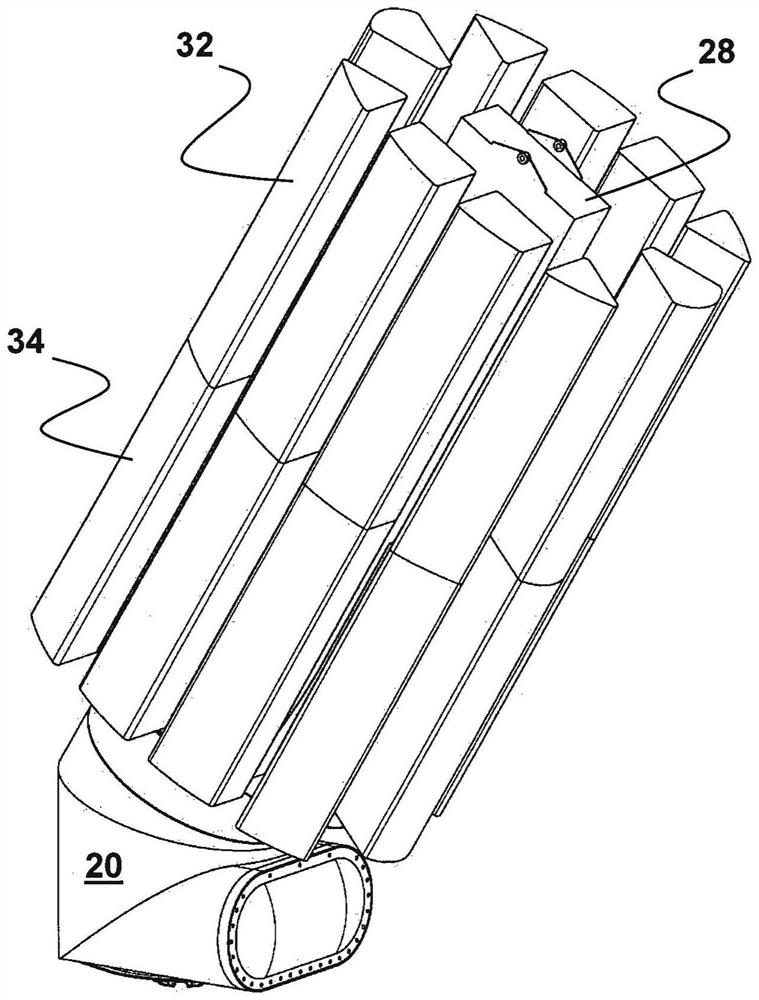
[0032] figure 1 A perspective view is shown of a first embodiment of a floating wind turbine according to the invention comprising a buoyancy body which is elliptical when viewed in cross section. The floating wind turbine 10 has a Y-shaped floating base 20 known from this type of turbine and has three buoyant bodies 30 attached to the arms 22, 24, 20 forming the base 20. 26 free ends. The buoyant body 30 is elliptical in cross-section and pulls the tower 40 of the wind turbine 10 with two energy conversion units by means of suitably provided cables 50 .

[0033] figure 2 show figure 1 An alternative design of wind turbine 10 is shown, which is a perspective view of a second embodiment of a floating wind turbine 10' according to the invention, a moving wind turbine 10' comprising buoyancy forces that are circular when viewed in cross section. Body 30. The floating wind turbine 10' also has a Y-shaped floating foundation 20 with three buoyancy bodies 30' fastened to the f...


PUM

PropertyMeasurementUnit
Diameteraaaaaaaaaa
Lengthaaaaaaaaaa

Abstract

The invention relates to a wind turbine (10) comprising a floating foundation (20) having a plurality of buoyancy bodies (30, 30'), the buoyancy bodies (30, 30') being formed from a plurality of buoyancy body elements (32, 32') designed as hollow bodies, which are arranged adjacent to one another in a first plane concentrically around each central element (28, 28') extending from the floating foundation (20) and are connected to said central element, and each buoyancy body element (32, 32', 34, 34') has a surface supported on the central element (28, 28'), a convex surface arranged opposite the central element (28, 28'), and two lateral surfaces each supported on a lateral surface of an adjacent buoyancy body element (32, 32', 34, 34').

Description

technical field [0001] The invention relates to a wind turbine comprising a floating foundation with a plurality of buoyancy bodies. Background technique [0002] A particularly advantageously designed floating wind turbine is known from EP 3 019 740 B1, which has a Y-shaped foundation extending in one plane and is designed to be buoyant by the arrangement of buoyancy bodies connected to the foundation . Although EP 3019 740 B1 does not contain any specific statement about the design of the buoyant body, other patent applications of the applicant, eg DE 10 2016 118 079 B3 or WO 2017 / 206976 A1, state that the buoyant body should advantageously be rigidly connected to the foundation. For example, the buoyant body may form an enclosure for a floating foundation made of concrete and itself may be made of steel. [0003] WO 2014 / 044453 A1 discloses another type of floating base in the form of a triangular base extending in a plane with steel Triangular planar multiple support ...

Claims


Application Information

Patent Timeline
IPC IPC(8): F03D13/25B63B35/44
CPCF03D13/25B63B35/44B63B2035/446Y02E10/727Y02E10/72F05B2240/95F05B2240/93F05B2280/6003B63B2231/52B63B1/04B63B5/24B63B2005/242
Inventor S·西格弗里德森
Owner AERODYN CONSULTING SINGAPORE PTE LTD
Why Eureka
Try Eureka