Shock absorption sole and shoe
A sole and bottom layer technology, which is applied in the field of soles and shoes, can solve the problems of bulky and thick sliding element structure, complex sliding element structure, and small horizontal force buffer force, so as to reduce the risk of injury, improve foot comfort, and reduce impact force Effect
- Summary
- Abstract
- Description
- Claims
- Application Information
AI Technical Summary
Problems solved by technology
Method used
Image

Examples
Embodiment 1
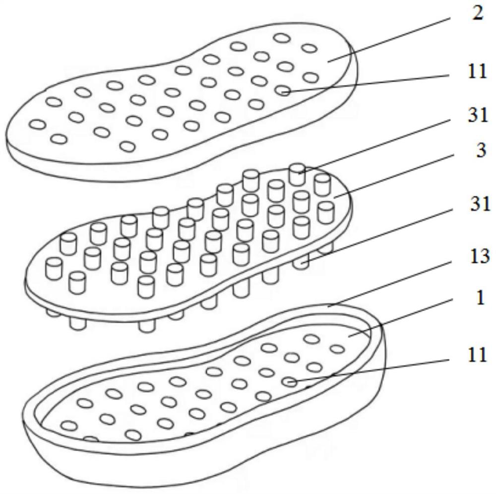
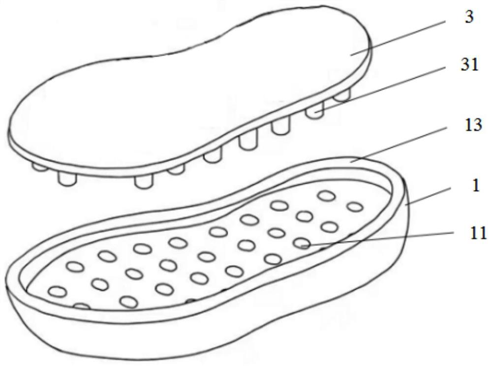
[0067] See attached Figure 1 to Figure 14 , a shoe sole for shock absorption, the shoe sole includes an adaptive cushioning layer 3 and a lower bottom layer 1 that are stacked;
[0068] One side of the adaptive cushioning layer 3 is arranged close to the vamp, and the side of the adaptive cushioning layer 3 away from the vamp is connected to the lower bottom layer 1;
[0069] The side of the adaptive buffer layer 3 facing the lower bottom layer 1 is provided with a raised structure;
[0070] The lower bottom layer 1 is provided with a limiting structure adapted to the raised structure;
[0071] After the position-limiting structure cooperates with the protruding structure, the self-adaptive buffer layer 3 can be elastically deformed under the action of external force.
[0072] It should be noted that: in this embodiment, an adaptive cushioning layer 3 capable of elastic deformation is provided in the sole, and the adaptive cushioning layer 3 is very soft under normal condit...
Embodiment 2
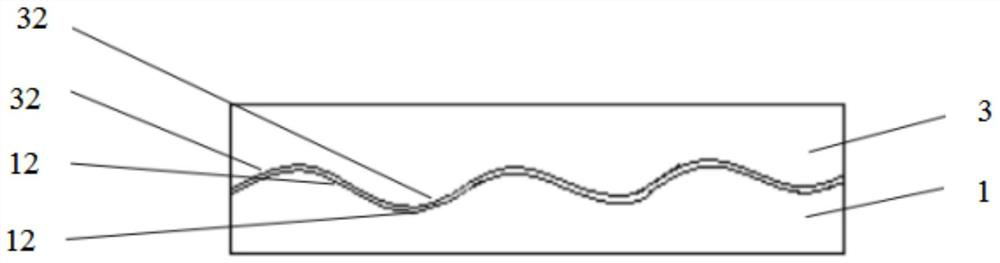
[0163] It should be noted that the main difference between this embodiment and Embodiment 1 is that in Embodiment 1, a gap is set between the protruding structure and its corresponding limiting structure, and there is no gap between the protruding structure and its corresponding limiting structure In this embodiment, a gap is set between the protruding structure and its corresponding limiting structure, and there is no gap between the protruding structure and its corresponding limiting structure.
[0164] Specifically, the protruding structure arranged toward the upper bottom layer 2 is adapted to the shape of the limiting structure;
[0165] And there is a gap between the protruding structure and its corresponding limiting structure.
[0166] In some possible embodiments, such as Figure 8 As shown, between the self-adaptive buffer layer 3 and the lower bottom layer 1, only the stop protrusion 31 is used to cooperate with the first receiving groove 11, and between the self-a...
Embodiment 3
[0169] It should be noted that the main difference between this embodiment and Embodiment 1 is that the adaptive buffer layer 3 in Embodiment 1 is composed of a first buffer part, a connection part and a second buffer part connected in sequence, while in this embodiment Among them, the adaptive buffer layer 3 includes a fixed part and a third buffer part;
[0170] The third buffer part is arranged around the fixed part, and no protruding structure is provided on the fixed part, and only the protruding structure is provided on the third buffer part.
[0171] In some possible embodiments, the third buffer portion is circular.
PUM
| Property | Measurement | Unit |
|---|---|---|
| Stiffness | aaaaa | aaaaa |
Abstract
Description
Claims
Application Information
 - R&D Engineer
- R&D Manager
- IP Professional
- Industry Leading Data Capabilities
- Powerful AI technology
- Patent DNA Extraction
Browse by: Latest US Patents, China's latest patents, Technical Efficacy Thesaurus, Application Domain, Technology Topic.
© 2024 PatSnap. All rights reserved.Legal|Privacy policy|Modern Slavery Act Transparency Statement|Sitemap