Mechanical clamping jaw

A mechanical gripper and clamping technology, applied in the field of mechanical grippers, can solve the problems of damage or falling off of the clamped parts, and achieve the effect of ensuring stable operation, eliminating the risk of falling, and ensuring firmness.

Inactive Publication Date: 2022-02-25
谢龙勤
View PDF0 Cites 0 Cited by
  • Summary
  • Abstract
  • Description
  • Claims
  • Application Information

AI Technical Summary

Problems solved by technology

[0004] The purpose of the present invention is to solve the problem that the jaws in the prior art are difficult to control the clamping force of the clamped parts, causing damage or falling off of the clamped parts, and propose a mechanical gripper

Method used


Image

  • Mechanical clamping jaw
  • Mechanical clamping jaw

Examples


Embodiment Construction

[0020] The following will clearly and completely describe the technical solutions in the embodiments of the present invention with reference to the accompanying drawings in the embodiments of the present invention. Obviously, the described embodiments are only some of the embodiments of the present invention, not all of them.

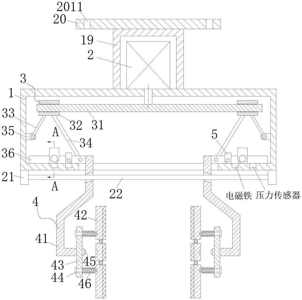
[0021] refer to Figure 1-2 , a mechanical gripper, comprising a fixed frame 1, a cylinder 2, a transmission module 3 and a clamping module 4, the cylinder 2, the transmission module 3 and the clamping module 4 are assembled and used on the basis of the fixed frame 1; wherein, the The cylinder 2 is fixed on the outside of the fixed frame 1, the output end of the cylinder 2 runs through the fixed frame 1 and is connected to the transmission module 3, and the cylinder 2 drives the clamping module 4 by driving the transmission module 3 to perform clamping work.

[0022] Specifically, the transmission module 3 is symmetrically arranged inside the fixed fram...


PUM


Abstract

The invention relates to the technical field of machinery, in particular to a mechanical clamping jaw which comprises a fixing frame, an air cylinder, a transmission module and a clamping module, and is characterized in that the air cylinder, the transmission module and the clamping module are assembled and used through the fixing frame. The air cylinder is fixed outside the fixing frame, the output end of the air cylinder penetrates through the fixing frame to be connected with the transmission module, and the air cylinder drives the transmission module to drive the clamping module to conduct clamping work. After an object is clamped, a reset switch is triggered in the process that the middle section of a clamping plate deforms and bends and sinks inwards, and through electric signal transmission and control among the reset switch, a controller, a pressure sensor and an electromagnet, the electromagnet embedded in the face, in sliding contact with the sliding plate, of the fixing frame is powered on, and the sliding plate is firmly adsorbed. Therefore, the problem that the sliding plate tilts up due to the fact that a clamping force arm is long in the object clamping process is solved, and the problem that the lower portion of the clamping plate is loosened is solved.

Description

technical field [0001] The invention relates to the technical field of machinery, in particular to a mechanical gripper. Background technique [0002] Machining refers to the process of changing the shape or performance of a workpiece through a mechanical device. According to the difference in processing methods, it can be divided into cutting processing and pressure processing. [0003] However, in actual use, there are still some shortcomings, such as the problem that the clamping force is difficult to control in the existing mechanical grippers. Set the clamping distance of the jaws to prevent damage to the objects while ensuring that the objects can be clamped. However, the size of the existing objects will have large and small deviations, which will cause damage to the jaws or cause damage to the jaws. If it falls off, it will affect the work efficiency, and then damage the quality of the object, and the damage of the object will lead to an increase in cost and a certa...

Claims


Application Information

Patent Timeline
Patent Type & Authority Applications(China)
IPC IPC(8): B25J15/02B25J13/08B25J15/08
CPCB25J15/0253B25J13/085B25J15/08
Inventor 谢龙勤林睿
Owner 谢龙勤
Why Eureka
Try Eureka