
Suspension bridge steel beam erecting method

A technology for suspension bridges and steel girders, applied in the direction of suspension bridges, bridge construction, bridges, etc., can solve problems affecting the stress state of bridges and the alignment of bridges, and achieve the effects of shortening the construction period, reducing installation stress, and reducing construction time

Active Publication Date: 2022-02-25
CHINA RAILWAY MAJOR BRIDGE ENG GRP CO LTD +1
View PDF3 Cites 0 Cited by
  • Summary
  • Abstract
  • Description
  • Claims
  • Application Information

AI Technical Summary

Problems solved by technology

[0005] The embodiment of the present invention provides a steel girder erection method of a suspension bridge to solve the problem of secondary internal force of the steel girder caused by the direct rigid connection of the steel girder segments in the related art, thereby affecting the stress state of the bridge and the bridge alignment

Method used


Image

  • Suspension bridge steel beam erecting method
  • Suspension bridge steel beam erecting method
  • Suspension bridge steel beam erecting method

Examples


Embodiment Construction

[0030] In order to make the purpose, technical solutions and advantages of the embodiments of the present invention clearer, the technical solutions in the embodiments of the present invention will be clearly and completely described below in conjunction with the drawings in the embodiments of the present invention. Obviously, the described embodiments It is a part of embodiments of the present invention, but not all embodiments. Based on the embodiments of the present invention, all other embodiments obtained by persons of ordinary skill in the art without making creative efforts belong to the protection scope of the present invention.

[0031] The embodiment of the present invention provides a steel girder erection method for a suspension bridge, which can solve the problem of directly rigidly connecting steel girder segments in the related art, which increases the difficulty of installation and generates secondary internal forces of the steel girder, thereby affecting the br...


PUM


Abstract

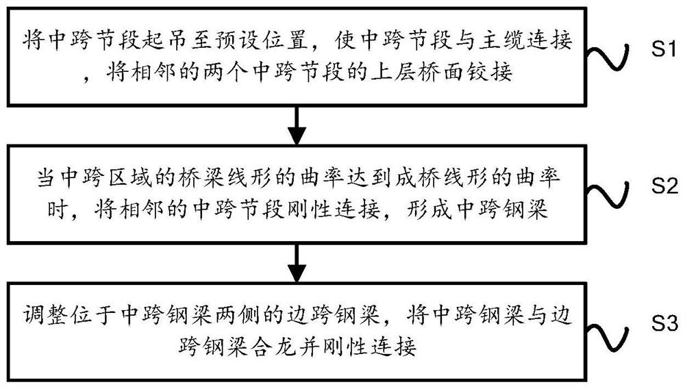
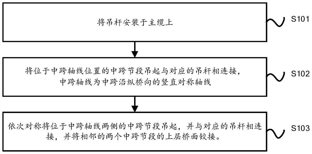
The invention relates to a suspension bridge steel beam erecting method which comprises the following steps that midspan steel beam sections are symmetrically erected section by section from the midspan to the two sides, and the adjacent midspan steel beam sections are hinged between upper-layer bridge floors; when the curvature of the bridge line shape of the erected mid-span area reaches the curvature designed into the bridge line shape, the erected mid-span sections are rigidly connected to form a whole; and closing of the side-span side steel beams and the middle-span steel beams is completed by adjusting the postures of the steel beams which are located on the two sides and connected into a whole. According to the suspension bridge steel beam erection method designed by the invention, the installation stress in the steel beam erection process is reduced, the installation quality of the bridge is improved, meanwhile, the erection of the side span steel beam section and the middle span steel beam section is independent, and the construction efficiency can be improved by reasonably arranging the steel beam erection procedure and optimizing the construction organization in a steel beam factory and on a construction site.

Description

technical field [0001] The invention relates to the field of bridge construction, in particular to a method for erecting steel beams of a suspension bridge. Background technique [0002] Due to its excellent spanning ability, suspension bridges are often used in long-span bridges. However, due to its navigation requirements across waters, it is impossible to use the bracket method to erect steel beams in waters. [0003] In order to facilitate transportation, the steel beam is often divided into multiple segments, and the erection of the steel beam is completed by assembling the steel beam segments at the construction site. [0004] With the vigorous development of high-speed rail bridges in my country, the scale of bridges has continued to increase, and the weight of steel beam segments has exceeded 1,000 tons. When the steel girders of suspension bridges are erected in a common way, that is, they are erected section by section and rigidly connected one by one. Since the ...

Claims


Application Information

Patent Timeline
Patent Type & Authority Applications(China)
IPC IPC(8): E01D21/08E01D11/02E01D19/00E01D19/16
CPCE01D21/08E01D11/02E01D19/00E01D19/16Y02E10/72
Inventor 冯广胜周功建王艳峰赵小静黄旺明涂满明姚发海李奔琦阮梦飞王瑞邓玉平刘亦奇程孝康徐胜
Owner CHINA RAILWAY MAJOR BRIDGE ENG GRP CO LTD
Learn More