Short-wave transmitter harmonic filtering unit state prediction device and method

A short-wave transmitter and harmonic filtering technology, applied in the direction of measuring devices, measuring electricity, measuring electrical variables, etc., can solve the problems affecting the availability of equipment, the burning of harmonic filtering units, and the inability of short-wave transmitters to work. Simple circuit and state prediction procedures, accurate state prediction results, and the effect of improving the failure detection rate

Pending Publication Date: 2022-02-25
NANJING PANDA HANDA TECH
View PDF0 Cites 0 Cited by
  • Summary
  • Abstract
  • Description
  • Claims
  • Application Information

AI Technical Summary

Problems solved by technology

Harmonic filter unit faults generally occur during use. The existing detection methods can only detect fault information during the transmitter’s transmission process or when the transmitter is turned on. If there is a band open circuit, short circuit, or relay contact If the band cannot be disconnected due to bonding or non-adhesion, it is difficult to detect the fault before the transmitter is launched, and there is a risk of burning the equipment when the short-wave transmitter is launched; the relay reaches the mechanical life, and the contact breaks and fails, which cannot be predicted in advance , causing the shortwave transmitter to fail to work or the harmonic filter unit to burn out, affecting the availability of equipment

Method used


Image

  • Short-wave transmitter harmonic filtering unit state prediction device and method
  • Short-wave transmitter harmonic filtering unit state prediction device and method
  • Short-wave transmitter harmonic filtering unit state prediction device and method

Examples


Embodiment

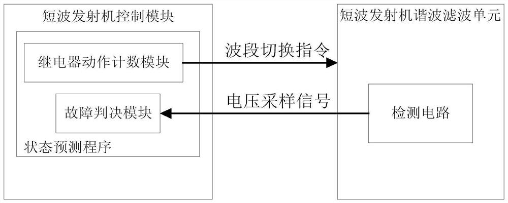
[0046] The state prediction device of the harmonic filter unit of the short-wave transmitter of the present invention, the principle block diagram is as follows figure 1 As shown, the shortwave transmitter control module and harmonic filter unit are inherent hardware of the shortwave transmitter

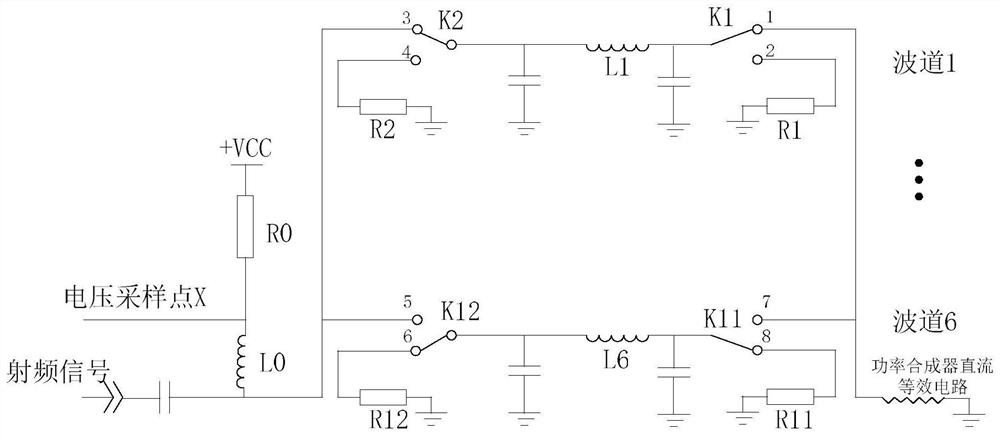
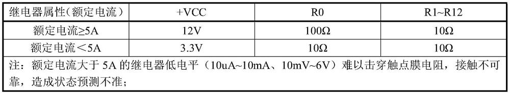
[0047] The detection circuit designed by the present invention is as figure 2 As shown, the shortwave operating frequency range is 2MHz to 29.9999MHz, and the harmonic filter unit is mainly used to filter out the harmonics of the operating frequency point. Table 1 is divided into 6 bands.

[0048] Table 1 Band-Frequency Relationship Table

[0049] band number Frequency (MHz) 1 2.0000~3.1408 2 3.1409~4.1325 3 4.1326~7.7459 4 7.7460~12.1642 5 12.1643~19.1027 6 19.1028~29.9999

[0050] When the working frequency falls on band 1 (the initial state of the shortwave transmitter is generally band 1), the controller of the shortwave transmitt...


PUM

PropertyMeasurementUnit
Resistanceaaaaaaaaaa

Abstract

The invention discloses a short-wave transmitter harmonic filtering unit state prediction device and method. The device comprises a detection circuit arranged in a short-wave transmitter harmonic filtering unit and a state prediction program unit arranged in a short-wave transmitter control module. The detection circuit is arranged at the radio frequency input end of the harmonic filtering unit, and radio frequency signals outputted by the harmonic filtering unit are synthesized by the power synthesizer and then outputted; the state prediction program unit comprises a relay action counting module and a fault judgment module; the relay action counting module counts the action times of a relay in the short-wave transmitter harmonic filtering unit; and the fault judgment module receives the voltage sampling signal output by the detection circuit, and judges and determines the state of the harmonic filtering unit. According to the invention, on-line detection can be carried out on the harmonic filtering unit fault to predict the residual life of the relay; when the harmonic filtering unit has a fault, a fault indication is given; when the relay is close to the mechanical service life, early warning and maintenance suggestions are given, and condition-based maintenance is achieved.

Description

technical field [0001] The invention belongs to the technical field of shortwave transmitters, in particular to a device and method for predicting the state of a harmonic filter unit of a shortwave transmitter. Background technique [0002] The harmonic filter unit of the short-wave transmitter mainly realizes the filtering of the input RF power signal, and suppresses the second and third harmonics within the index range. The harmonic filter unit is generally divided into several bands. According to the operating frequency of the short-wave transmitter (2MHz~30MHz), the bands (usually 6 bands and 12 relays) are switched through relays to realize harmonic filtering of input RF signals. [0003] According to historical maintenance data, the failure modes of the harmonic filter unit mainly include faults such as band open circuit, band short circuit, and band cannot be disconnected. If the fault cannot be detected effectively, it will cause the harmonic filter unit or the core...

Claims


Application Information

Patent Timeline
IPC IPC(8): G01R31/00G01R31/327
CPCG01R31/003G01R31/3278
Inventor 马赛蒋敏涛张瑞祥李宏哲
Owner NANJING PANDA HANDA TECH
Why Eureka
Try Eureka