Conveying mechanism

A conveying mechanism and conveyor belt technology, which is applied in the direction of conveyor objects, transportation and packaging, electrical components, etc., can solve the problems of linear module design waste, etc., and achieve the effects of avoiding stroke design waste, saving power, and avoiding design waste

Pending Publication Date: 2022-02-25
赛姆柯(苏州)智能科技有限公司
View PDF0 Cites 0 Cited by
  • Summary
  • Abstract
  • Description
  • Claims
  • Application Information

AI Technical Summary

Problems solved by technology

[0004] The purpose of the present invention is to provide a conveying mechanism to solve the problem of waste in the existing linear module design when the load size increases

Method used


Image

  • Conveying mechanism
  • Conveying mechanism
  • Conveying mechanism

Examples


Embodiment Construction

[0025] The technical solutions of the present invention will be clearly and completely described below in conjunction with the accompanying drawings. Apparently, the described embodiments are some of the embodiments of the present invention, but not all of them. Based on the embodiments of the present invention, all other embodiments obtained by persons of ordinary skill in the art without making creative efforts belong to the protection scope of the present invention.

[0026] In the description of the present invention, it should be noted that the terms "center", "upper", "lower", "left", "right", "vertical", "horizontal", "inner", "outer" etc. The indicated orientation or positional relationship is based on the orientation or positional relationship shown in the drawings, and is only for the convenience of describing the present invention and simplifying the description, rather than indicating or implying that the referred device or element must have a specific orientation, ...


PUM


Abstract

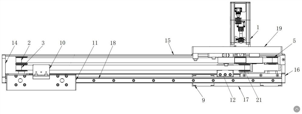
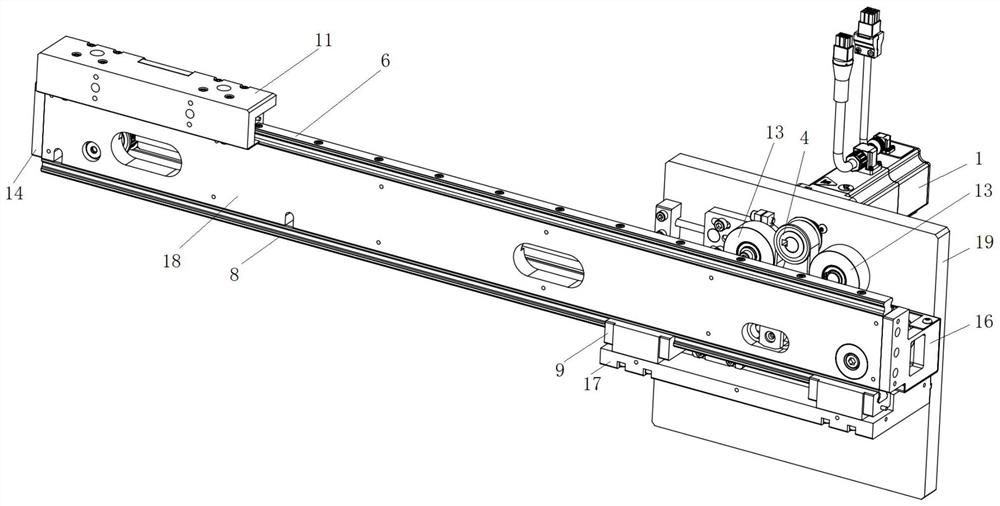
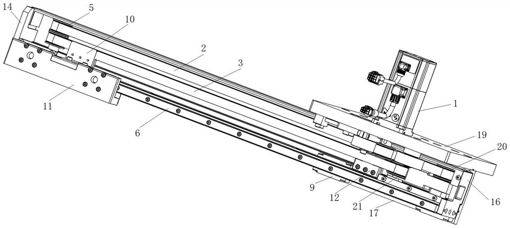
The invention relates to a conveying mechanism which comprises a driving part, a transmission assembly, a first displacement assembly, a second displacement assembly, a first connecting assembly and a second connecting assembly. The transmission assembly comprises a first conveying belt and a second conveying belt, and the driving part is used for driving the first conveying belt and driving the second conveying belt to operate synchronously; the first connecting assembly is connected with the first displacement assembly and used for supporting a product, and the second connecting assembly is connected with the second displacement assembly; the first displacement assembly is connected with the second conveying belt through the first connecting assembly, the second displacement assembly is connected with the second conveying belt through the second connecting assembly, and the second conveying belt is used for driving the first displacement assembly to move products and driving the second displacement assembly to move; and the moving direction of the first displacement assembly is opposite to that of the second displacement assembly. According to the conveying mechanism, double strokes are achieved through one driving component, power is saved, efficiency is improved, and the equipment size is reduced; and different loads are flexibly compatible, and waste of traditional module load design is avoided.

Description

technical field [0001] The invention relates to a conveying mechanism. Background technique [0002] At present, the photovoltaic diffusion equipment first transports the silicon wafer and quartz boat from the feeding and discharging module to the transfer platform for placement. When the process furnace needs to be processed, the vertical transport module and the horizontal transport module cooperate to transfer the silicon wafer and quartz. The boat is transported to the oars, and the modules that carry the silicon wafers on the oars are horizontally transported to the modules of the dual-module drive mechanism. The size is large. [0003] With the substantial increase in the size of silicon wafers and the substantial increase in production capacity, the size of the module also needs to be increased accordingly to meet the increased weight and stroke, and the size of the module is standard, and it is practical to choose a module that can withstand the load. It may be far...

Claims


Application Information

Patent Timeline
Patent Type & Authority Applications(China)
IPC IPC(8): H01L21/677
CPCH01L21/67706
Inventor 吴建芬任俊江薇儿妮卡·夏丽叶张灵肖益波
Owner 赛姆柯(苏州)智能科技有限公司
Why Eureka
Try Eureka