Part placing frame device for automobile part welding

A technology for auto parts and components, which is applied in the direction of tool storage devices, drying gas arrangement, dryers, etc., which can solve the problems of parts that cannot be placed in layers, affect the use effect, and be inconvenient to find, etc., so as to reduce the occupied area , easy to replace, easy to layer the effect of placement

Pending Publication Date: 2022-03-01
阜阳常阳汽车部件有限公司
View PDF6 Cites 2 Cited by
  • Summary
  • Abstract
  • Description
  • Claims
  • Application Information

AI Technical Summary

Problems solved by technology

[0003] Most of the auto parts welding parts racks currently on the market cannot arrange the parts in layers in an orderly manner, which may cause most parts to be stacked together, which is inconvenient for the staff to find and affects the use effect. At the same time, when the device is placed, the moisture inside the device can be removed, which may cause the parts to rust and affect the use effect. Therefore, in view of the above problems, a parts placing rack device for auto parts welding is proposed

Method used


Image

  • Part placing frame device for automobile part welding
  • Part placing frame device for automobile part welding
  • Part placing frame device for automobile part welding

Examples


Embodiment 1

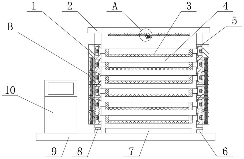
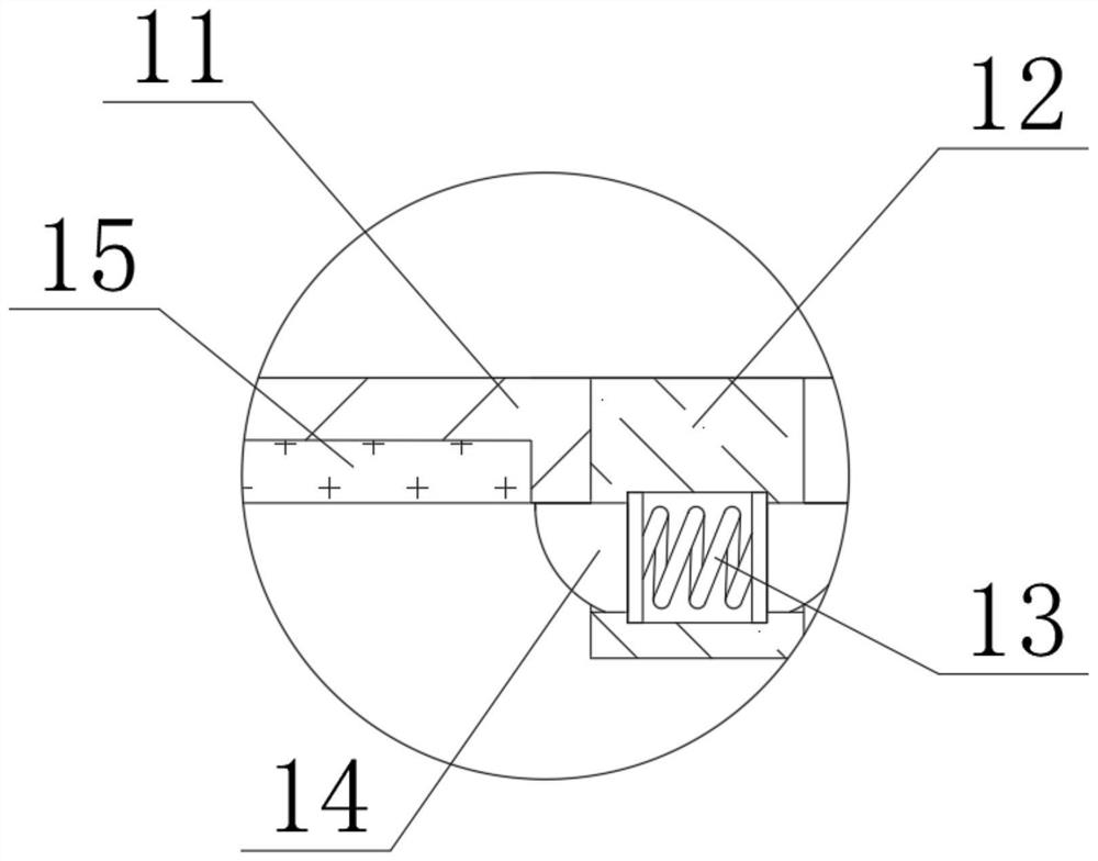
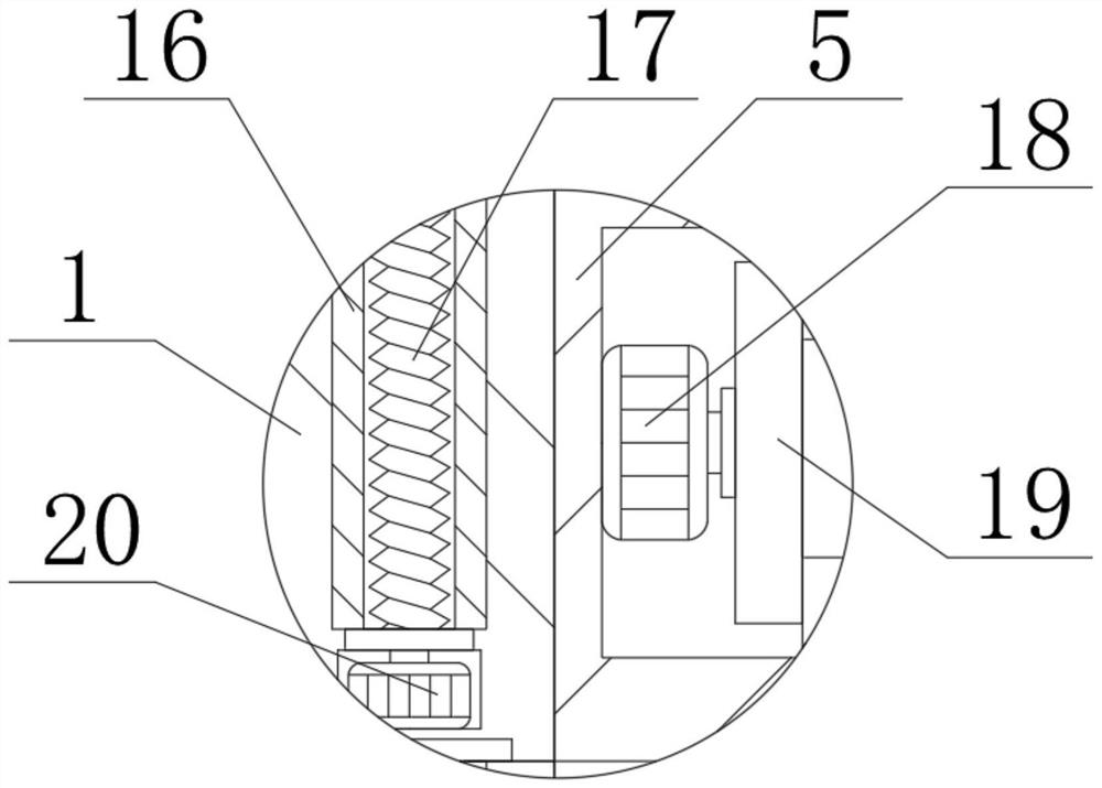
[0033] see Figure 1-6 , the present invention provides a technical solution:

[0034] A component placing rack device for auto parts welding, comprising a placing box 3, a lifting frame 5 and a bottom plate 9, the upper side of the right end of the bottom plate 9 is provided with a placing box 3, and the upper sides of the left and right ends of the placing box 3 are fixedly connected There is a turret 19, the turret 19 is rotatably connected in the lifting frame 5, the lifting frame 5 is arranged on the left and right sides of the placement box 3, and the lifting plate 1 is fixedly connected to the end of the lifting frame 5 away from the placement box 3, so The upper side of the lifting plate 1 is slidingly connected with a driving plate 16, and the driving plate 16 is fixedly connected to the bottom end of another lifting plate 1, and the bottom side of the driving plate 16 is provided with a threaded groove, and the driving plate 16 A threaded rod 17 is spirally connecte...

Embodiment 2

[0038] see Figure 7-8 , the present invention provides a technical solution:

[0039] The bottom end of lifting frame 5 is fixedly connected with support rod 25, and support rod 25 is provided with a plurality of, and support rod 25 is slidably connected in buffer frame 28 upper side, and buffer frame 28 is fixedly connected on the base plate 9, and buffer frame 28 is provided with Air chamber 27, air chamber 27 is provided with a plurality of, a plurality of air chambers 27 are connected through through chamber 29, and the upper side of air chamber 27 is sealed with piston plate 26, and the upper end of piston plate 26 is fixedly connected with support rod 25, and The front end of the chamber 27 is sealed with an air injection pipe 31, which is fixedly connected in the buffer frame 28, and the air injection pipe 31 is sealed with a check valve 30, through the air chamber 27 and the piston plate 26, the energy on the device can be absorbed , to increase the stability of the ...


PUM


Abstract

The invention relates to the technical field of automobile part welding, in particular to a part containing frame device for automobile part welding, which comprises a containing box, a lifting frame and a bottom plate, the containing box is arranged on the upper side of the right end of the bottom plate, rotating frames are fixedly connected to the upper sides of the left end and the right end of the containing box, and the rotating frames are rotatably connected into the lifting frame; the lifting frames are arranged on the left side and the right side of the containing box, a lifting plate is fixedly connected to the ends, away from the containing box, of the lifting frames, and a driving plate is slidably connected to the interior of the upper side of the lifting plate. The threaded rod can be matched with the driving plate to enable the lifting plate to ascend and descend, so that the needed containing box can be automatically leaked out, workers can conveniently and rapidly find the needed containing box, the occupied area of the device can be reduced during containing, and meanwhile layered containing can be conveniently achieved.

Description

technical field [0001] The invention relates to the technical field of auto parts welding, in particular to a parts placing rack device for auto parts welding. Background technique [0002] Auto parts are the units that constitute the whole of auto parts processing and the products that serve the processing of auto parts. As the foundation of the auto industry, auto parts are a necessary factor to support the sustainable and healthy development of the auto industry, especially the current auto industry is in full swing. The independent development and innovation carried out requires a strong parts system as support. Therefore, the demand for a parts placing rack device for welding auto parts is increasing day by day. [0003] Most of the auto parts welding parts racks currently on the market cannot arrange the parts in layers in an orderly manner, which may cause most parts to be stacked together, which is inconvenient for the staff to find and affects the use effect. At th...

Claims


Application Information

Patent Timeline
Patent Type & Authority Applications(China)
IPC IPC(8): B25H3/04F26B21/00
CPCB25H3/04F26B21/00
Inventor 聂广辉
Owner 阜阳常阳汽车部件有限公司
Why Eureka
Try Eureka