High-speed single gravure printing machine

A printing machine, high-speed technology, applied in the field of high-speed single gravure printing machine, can solve the problems of insufficient ink scraping of the gravure cylinder, easy tilting of the doctor blade, troublesome operation, etc., to achieve easy replacement and maintenance, easy installation and operation , adjust the effect in time

Inactive Publication Date: 2022-03-01
张丹丹
View PDF0 Cites 0 Cited by
  • Summary
  • Abstract
  • Description
  • Claims
  • Application Information

AI Technical Summary

Problems solved by technology

[0004] Aiming at the deficiencies of the prior art, the present invention provides a high-speed single gravure printing machine, which solves the problem that the scraper blade is prone to tilt after a long time of use of the gravure printing machine currently used, so that the local area ink on the gravure cylinder is scraped off. It is not thorough enough, it needs to be recalibrated before it can be used, and the operation is more troublesome

Method used


Image

  • High-speed single gravure printing machine
  • High-speed single gravure printing machine
  • High-speed single gravure printing machine

Examples


Embodiment 1

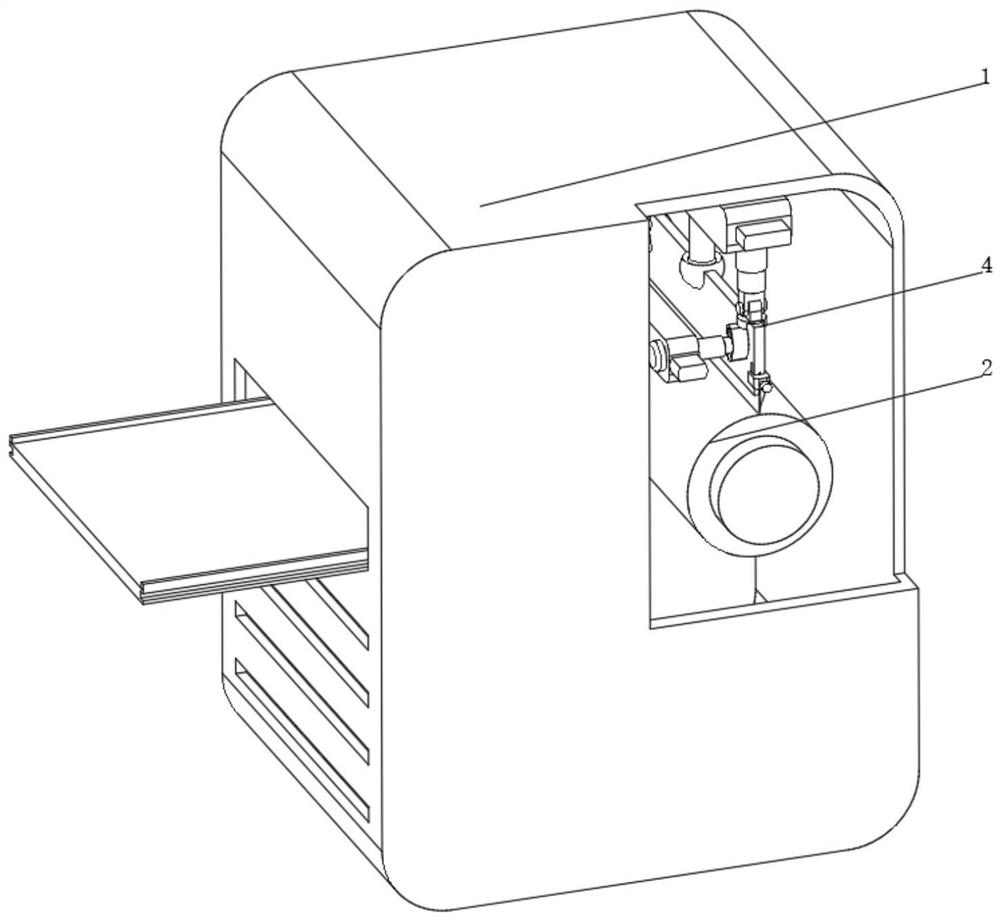
[0035] see Figure 1-2 , the present invention provides a technical solution: a high-speed single gravure printing machine, specifically comprising:

[0036] A printing machine body 1, the printing machine body 1 is provided with a gravure cylinder 2 inside, and both ends of the gravure cylinder 2 are provided with a fixing frame 3, and the fixing frame 3 is fixed on the inner wall of the printing machine body 1;

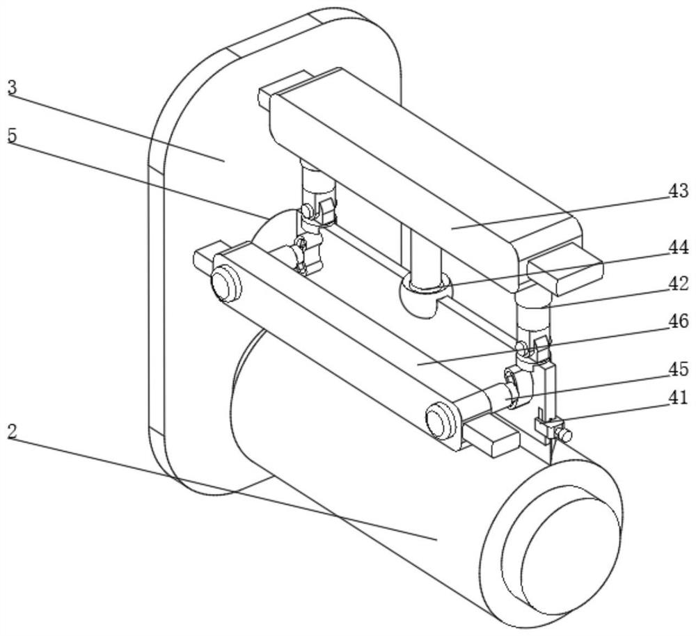
[0037] A scraper device 4, the scraper device 4 is arranged on the part above the gravure cylinder 2 on the fixed frame 3, and the fixed frame 3 and the side of the printing machine body 1 are provided with an installation port 5;

[0038] Scraper device 4 comprises:

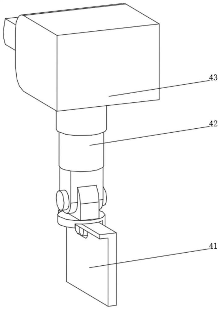
[0039] Fixed knife seat 41, the two ends of the top of the fixed knife seat 41 are connected with a hydraulic telescopic rod 42 through a rotating seat, the top of the hydraulic telescopic rod 42 is fixedly connected with a fixed seat 43, and the center position of the bottom of the fixed seat 43 is ...

Embodiment 2

[0043] see Figure 1-4 On the basis of Embodiment 1, the present invention provides a technical solution: the fixed knife seat 41 includes a base 411, and the bottom of the base 411 is provided with a mounting groove 412, and one side of the mounting groove 412 is slidingly connected to a splint 413, and the inner wall of the mounting groove 412 is slidingly connected There is an ink scraper 414, a chuck 415 is slidably connected to one side of the base 411, a claw 416 is slidably connected to the inner wall of the chuck 415, and a threaded push rod 417 is connected to one side of the claw 416 in rotation, and the threaded push rod 417 is far away from the claw 416. One end passes through the collet 415 and is threadedly connected with the collet 415 , the collet 415 is connected to the base 411 through a limiting groove and can only slide up and down on the side of the base 411 .

[0044] A fixed knife seat 41 is provided, and the scraper 414 can be installed through the inst...

Embodiment 3

[0046] see Figure 1-5 On the basis of Embodiment 1 and Embodiment 2, the present invention provides a technical solution: the control device 45 includes a slideway 451, the inner wall of the slideway 451 is slidably connected with a connecting push rod 452, and the connecting push rod 452 is far away from the side of the slideway 451. One end runs through and is slidably connected with a control sleeve 453, the bottom of the inner wall of the control sleeve 453 is fixedly connected with a sub-switch 454, and one end of the connecting push rod 452 located inside the control sleeve 453 is fixedly connected with a female switch 455, and the connecting push rod 452 is connected to the control sleeve. A buffer spring 456 is arranged between the tubes 453, one side of the slideway 451 is fixedly connected to the side of the fixed knife seat 41, and the end of the control sleeve 453 away from the connection push rod 452 is fixedly connected to the side of the control seat 46, and a c...


PUM


Abstract

The high-speed single gravure printing machine specifically comprises a printing machine body, a gravure cylinder is arranged in the printing machine body, fixing frames are arranged at the two ends of the gravure cylinder, and the fixing frames are fixed to the inner wall of the printing machine body; the scraper device is arranged on the portion, located above the gravure cylinder, of the fixing frame, and mounting openings are formed in the side faces of the fixing frame and the printing machine body; the scraper device comprises a fixed tool apron, hydraulic telescopic rods are connected to the two ends of the top of the fixed tool apron through rotating seats, a fixed seat is fixedly connected to the tops of the hydraulic telescopic rods, and the center of the bottom of the fixed seat is connected with the fixed tool apron through a universal rotating device. According to the high-speed single gravure printing machine, the levelness of the scraper can be judged through the friction force between the scraper and the gravure cylinder, self-adaptive adjustment is carried out, judgment and recognition are more accurate, adjustment is more timely, and the machining efficiency of the device is higher.

Description

technical field [0001] The invention relates to the technical field of printing machines, in particular to a high-speed single-gravure printing machine. Background technique [0002] A printing press is a machine that prints text and images. Modern printing machines are generally composed of plate loading, ink application, embossing, paper feeding and other mechanisms. Its working principle is: first make the printing plate of the text and image to be printed, install it on the printing machine, and then apply the ink to the place where the text and image are on the printing plate manually or by the printing machine, and then transfer it directly or indirectly Printing on paper or other substrates, so as to reproduce the same printed matter as the printing plate, the invention and development of printing presses play an important role in the spread of human civilization and culture. After the gravure printing machine currently used is used for a long time, the doctor blade...

Claims


Application Information

Patent Timeline
Patent Type & Authority Applications(China)
IPC IPC(8): B41F9/00B41F9/10F16F15/067
CPCB41F9/00B41F9/10B41F9/1036F16F15/067
Inventor 张丹丹
Owner 张丹丹
Why Eureka
Try Eureka