Electric control opening device for automotive escape sunroof and control method of electric control opening device
A technology of opening device and skylight, applied in the field of automobile escape skylight structure, can solve the problems of poor safety and reliability of escape skylight, and achieve the effects of simple structure, convenient lubrication and structural safety
- Summary
- Abstract
- Description
- Claims
- Application Information
AI Technical Summary
Problems solved by technology
Method used
Image
Examples
Embodiment 1
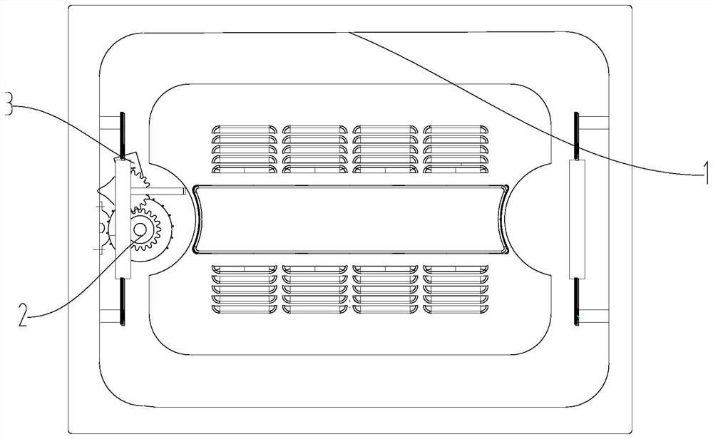
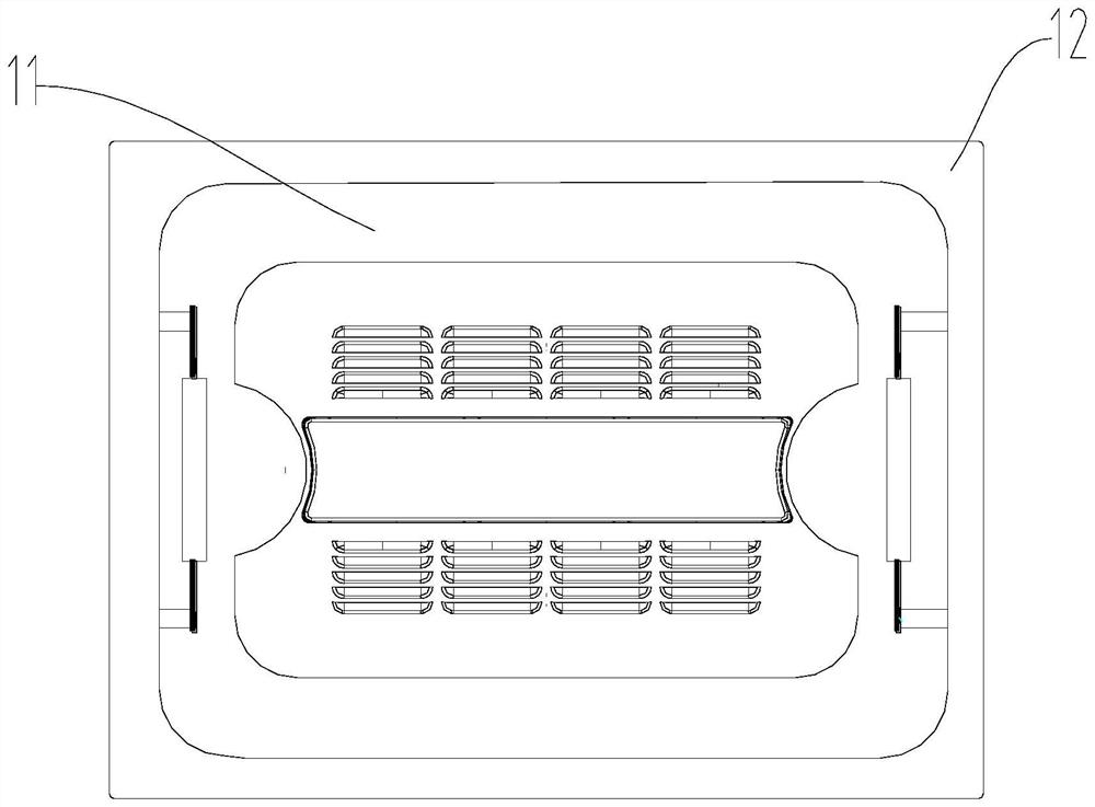
[0054] see Figure 1 to Figure 9 , an electric control opening device for a vehicle escape sunroof, comprising: a sunroof assembly 1, the sunroof assembly 1 includes a middle frame 11, a top cover 12, the right side of the top cover 12 is hinged to the right side of the middle frame 11 , the vehicle escape sunroof electric control opening device also includes an electric opening assembly 2, a separation assembly 3, and a control module 4;
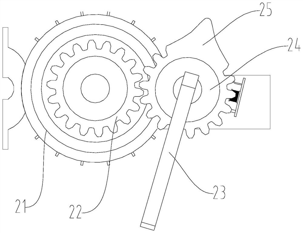
[0055] The electric opening assembly 2 includes a motor 21, a driving gear 22, and a locking pin 23. The motor 21 is fixedly installed on the left side of the middle frame 11, and the driving gear 22 is installed on the output shaft of the motor 21. One end of the locking pin 23 is provided with a locking gear 24, and the outer peripheral surface of the locking gear 24 protrudes from the left side of the middle frame 11 to form a tip 25. The locking gear 24 and the driving gear 22 The left side of the middle frame 11 is provided with a thr...
Embodiment 2
[0062] Basic content is the same as embodiment 1, the difference is:
[0063] One end of the electromagnet fixing rod 36 is provided with a U-shaped groove, and a rotating pin 315 is arranged in the U-shaped groove. The electromagnet swing rod 35 includes a connecting portion and a hook portion connected to each other, and the connecting portion is long. Bar shape, the bottom of the connection part is provided with a rotation hole, the connection part is connected to the electromagnet fixing rod 36 through the rotation pin 315 rotation, the hook part is connected with the spring 39, and the connection There is a chute 310 on the outside of the connection part, the magnet 314 is fixedly connected to the inside of the connection part, and the end of the push rod 34 away from the ferrule 38 is fixedly connected to a slider 311, and the slider 311 is installed on The inside of the chute 310, the chute 310 is a cross-shaped groove, the cross-shaped groove includes a horizontal groo...
Embodiment 3
[0065] Basic content is the same as embodiment 1, the difference is:
[0066] The cross-section of the tip 25 is triangular, and the two sides of the triangle are concave arc-shaped.
PUM
 Abstract
Description
Claims
Application Information
 - R&D
- Intellectual Property
- Life Sciences
- Materials
- Tech Scout
- Unparalleled Data Quality
- Higher Quality Content
- 60% Fewer Hallucinations
Browse by: Latest US Patents, China's latest patents, Technical Efficacy Thesaurus, Application Domain, Technology Topic, Popular Technical Reports.
© 2025 PatSnap. All rights reserved.Legal|Privacy policy|Modern Slavery Act Transparency Statement|Sitemap|About US| Contact US: help@patsnap.com


