Supercharge Your Innovation With Domain-Expert AI Agents!

Mining elevator escape device

An escape device and elevator technology, which is applied to elevators, transportation and packaging, elevators and other directions in buildings, can solve the problems of lack of fast escape devices, worker safety threats, and inability to ensure the safety of mining elevators. Survival chance, guaranteed safety, effect of increasing stability

Pending Publication Date: 2022-03-01
苏迅电梯有限公司
View PDF4 Cites 0 Cited by
  • Summary
  • Abstract
  • Description
  • Claims
  • Application Information

AI Technical Summary

Problems solved by technology

[0003] The purpose of the present invention is to solve at least one of the technical problems existing in the prior art, and to provide a mine elevator escape device, which can solve the problem that most of the mine elevators do not have a quick escape device, so that it is impossible to ensure the safety of the mine elevator. The safety in use will pose a certain threat to the safety of workers

Method used


Image

  • Mining elevator escape device
  • Mining elevator escape device
  • Mining elevator escape device

Examples


Embodiment 1

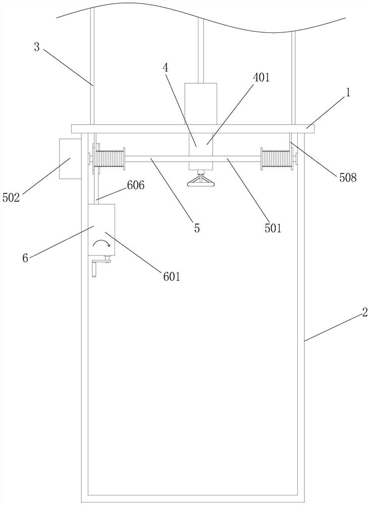
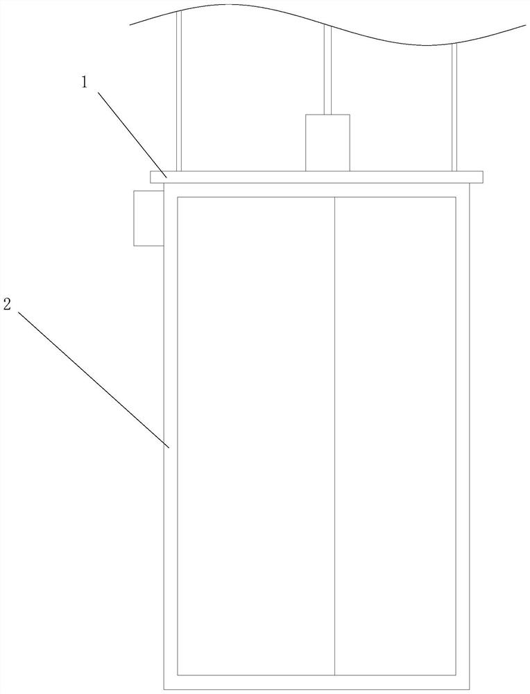
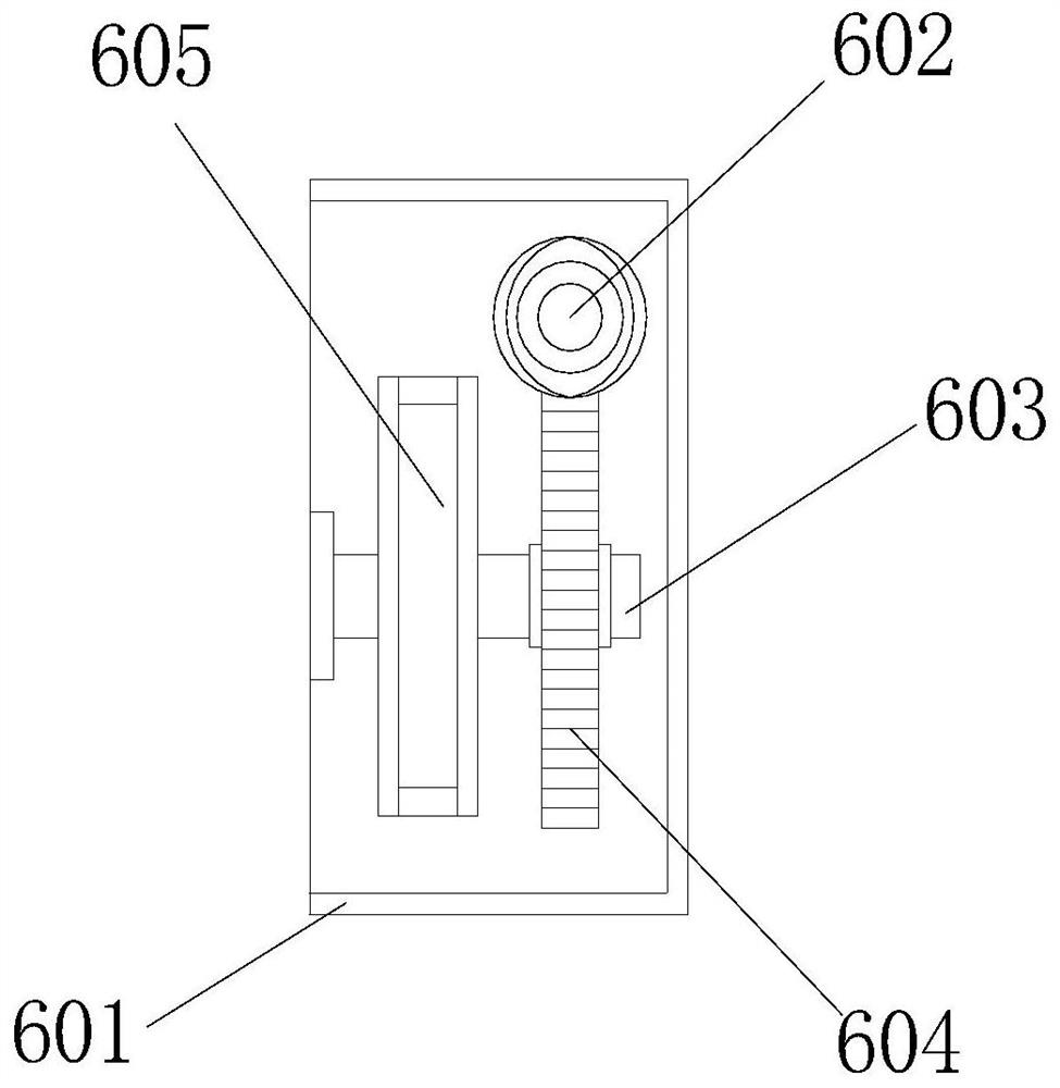
[0030] see Figure 1-6 , the present invention provides a technical solution: a mining elevator escape device, comprising a car roof 1, a connecting mechanism 4, a traction mechanism 5 and a rotating mechanism 6, a car body 2 is arranged below the car roof 1, and the car The top of top plate 1 is fixedly installed with the first traction cable 3, and connecting mechanism 4 comprises connecting box 401, installs horizontal plate 402 and connecting screw rod 403. 504, a second pulley 505, a rotating shaft 506, a first belt 507 and a second traction cable 508.

[0031] Further, the rear side of the connection box 401 is fixedly installed with the rear inner wall of the car body 2, and the inner walls of both sides of the connection box 401 are fixedly installed with a mounting horizontal plate 402, and the bottom of the mounting horizontal plate 402 is screwed with a connecting screw 403. One end of the screw rod 403 is fixedly equipped with a rotating handle, and the rotating h...

Embodiment 2

[0035] see Figure 1-6 , on the basis of the first embodiment, the bottom of the car roof 1 is provided with a threaded groove matching the connecting screw 403, and the top of the connecting screw 403 extends to the top of the mounting horizontal plate 402 and is threadedly installed in the threaded groove, This arrangement can connect the car roof 1 and the car body 2 through the connecting screw 403 when not in use, and can separate it through the connecting screw 403 when an emergency occurs. Such a structure is simple, easy to operate, and can effectively Avoid workers operating in a panic.

[0036] Further, a door is movably installed on the front side of the car body 2, and the setting of the door ensures the safety of workers when taking the elevator.

[0037] Furthermore, the outer wall of the rotating rod 501 is fixedly equipped with a circular limiting plate, which can limit the second traction cable 508 to prevent the second traction cable 508 from causing Windin...


PUM


Abstract

The invention discloses a mining elevator escape device, and relates to the technical field of mining elevators. The mining elevator escape device comprises a lift car top plate, a connecting mechanism, a traction mechanism and a rotating mechanism, a lift car body is arranged below the lift car top plate, and a first traction steel cable is fixedly installed at the top of the lift car top plate. According to the mine elevator escape device, through cooperative use of the mounting transverse plate and the connecting screw rod, the lift car top plate and the lift car body can be connected, in this way, in the normal use process, the situation that shaking is generated between the lift car top plate and the lift car body can be effectively avoided, and therefore the stability between the lift car top plate and the lift car body is improved; when people need to be trapped in the lift car body, the lift car top plate and the lift car body can be separated by rotating the connecting screw rod, and then the lift car body is moved, so that when the lift car body moves to a lower position and breaks down, self-rescue can be carried out, people can escape quickly, and the survival probability of the people is increased.

Description

technical field [0001] The invention relates to the technical field of mine elevators, in particular to an escape device for mine elevators. Background technique [0002] Because of its complex environment, mines have always been a high-incidence point of various major accidents, the most important of which is the mine elevator used in the mine. Once an accident or failure occurs in the mine elevator, it is difficult to protect the personnel inside the mine elevator. Rescue, when the mining elevator fails, the workers inside the mining elevator for a long time may cause the elevator to fall or rush to the top of the dangerous situation, but most of the mining elevators do not have a quick escape device, so there is no It can ensure the safety of the mine elevator in use, which will pose a certain threat to the safety of workers. Contents of the invention [0003] The purpose of the present invention is to solve at least one of the technical problems existing in the prior ...

Claims


Application Information

Patent Timeline
Patent Type & Authority Applications(China)
IPC IPC(8): B66B11/02B66B5/02
CPCB66B11/0226B66B5/027
Inventor 冯斌周建平丁威曹萍程毅倪月肖周建林
Owner 苏迅电梯有限公司
Features
  • R&D
  • Intellectual Property
  • Life Sciences
  • Materials
  • Tech Scout
  • Unparalleled Data Quality
  • Higher Quality Content
  • 60% Fewer Hallucinations
Learn More