Unlock instant, AI-driven research and patent intelligence for your innovation.
5G smart lamp
What is Al technical title?
Al technical title is built by PatSnap Al team. It summarizes the technical point description of the patent document.
A smart, 5G technology, applied in the 5G field, can solve the problems of shaking of 5G smart street lights, blurred vision of 5G smart street lights monitoring, and deviation of the vertical center of gravity of 5G smart street lights from light poles.
Inactive Publication Date: 2020-10-23
陈志全
View PDF0 Cites 5 Cited by
Summary
Abstract
Description
Claims
Application Information
AI Technical Summary
This helps you quickly interpret patents by identifying the three key elements:
Problems solved by technology
Method used
Benefits of technology
Problems solved by technology
[0003] Since the monitoring equipped on 5G smart street lights usually extends laterally and sideways, and is connected through a single connecting rod, if 5G smart street lights are installed on both sides of an upwardly inclined road, the overall 5G smart street lights will be slightly tilted, so that the 5G smart street lights The vertical center of gravity will deviate from the light pole, which will cause the 5G smart street lamp to shake when a large vehicle passes by, which will cause the monitoring on the 5G smart street lamp to have a blurred vision.
Method used
Image
Click on the blue label to locate the original text in one second.
Reading with bidirectional positioning of images and text.
Examples
Embodiment 1
[0027] For example figure 1 -example Figure 5 Shown:
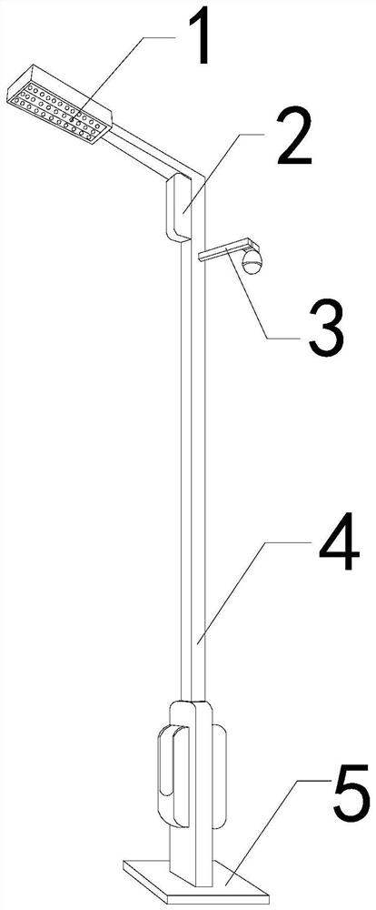
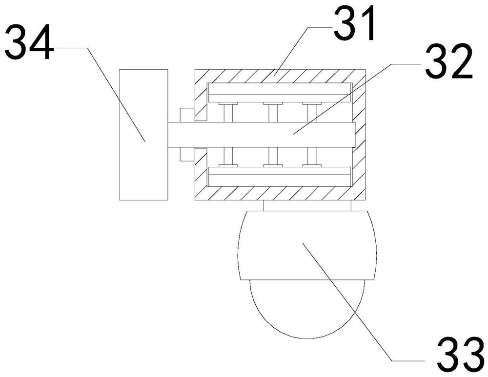
[0028] The invention provides a 5G smart lamp, the structure of which includes a lamp 1, a signalprocessing terminal 2, a monitor 3, a lamp post 4, and a base 5. The lamp 1 is electrically connected to the lamp post 4, and the signal processing terminal 2 is connected to the lamp post. 4-phase welding, the light pole 4 is fixed on the upper end of the base 5, and the monitor 3 is embedded and connected with the light pole 4; the monitor 3 includes a connecting rod 31, an outer frame 32, a linkage mechanism 33, and a camera end 34, The outer frame 32 runs through the inner part of the outer frame 32 , the linkage mechanism 33 is installed at the lower end of the connecting rod 31 , and the camera end 34 is connected with the outer frame 32 .
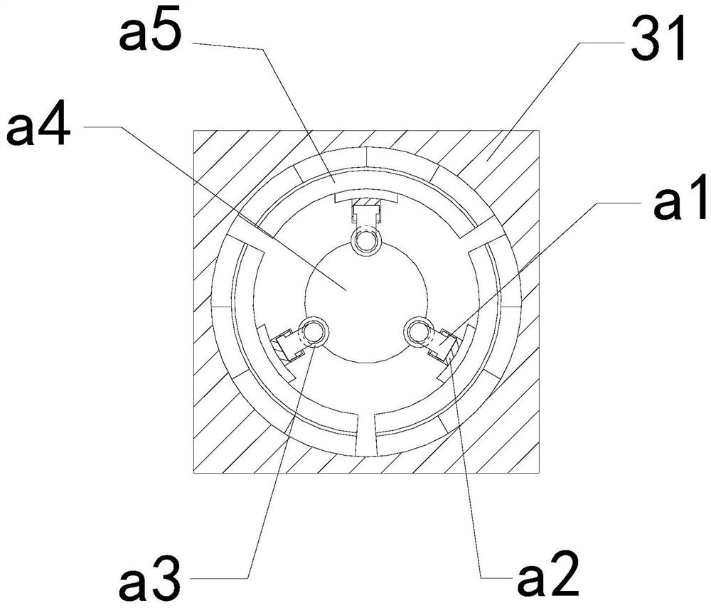
[0029] Wherein, the outer frame 32 includes a movable rod a1, a guide frame a2, an engaging ring a3, a linkage rod a4, and a force plate a5. One end of the movable rod a1 is in cl...
Embodiment 2
[0035] For example Figure 6 -example Figure 9 Shown:
[0036] Wherein, the linkage rod a4 includes a rod body c1, a cleaning brush c2, a driving mechanism c3, a booster end c4, a bottom plate c5, and a protective surface c6. The cleaning brush c2 is embedded in the front end of the driving mechanism c3. The end c4 drives the mechanism c3 to connect with the base plate c5 through the protective surface c6, the booster end c4 is installed between the drive mechanism c3 and the base plate c5, the base plate c5 is embedded and connected with the rod body c1, and the booster end c4 is The "X" shape structure, through the sway introduced from the outside of the mechanism, can make the booster end c4 swing and close inward during the sloshing, so that the overall length of the booster end c4 will be along, so that the booster end c4 can be downward Promote the driving mechanism c3.
[0037] Wherein, the driving mechanism c3 includes an outer belt frame c31, a rolling ball c32, a...
PUM
Abstract
The invention discloses a 5G smartlamp, which structurally comprises a lamp body, a signalprocessing end, a monitor, a lamp post and a base. The lamp body is electrically connected with the lamp post; the signalprocessing end is welded with the lamp post; the lamp post is fixed to the upper end of the base. The monitor is fixedly connected with the lamp post in an embedded mode. Whenlarge vehicles pass at two sides of the inclined road to result in shaking of the lamp post, shaking force on the lamp pole can be transmitted to the linkage rod on the outer frame through the camera shooting end; therefore, the movable rod on the linkage rod can transmit the rotating force of the linkage rod to the stressed plate; therefore, the contact block on the stressed plate can buffer and counteract the force conducted on the linkage rod; through the shaking force conducted by the camera shooting end, the boosting end on the linkage rod can inwards swing and be closed along the center of the linkage rod, so that the boosting end can forwards push the driving mechanism to move forwards, and a clearing brush on the driving mechanism can clear away dust attached to the outer surfaces of the connecting rod and the outer frame.
Description
technical field [0001] The present invention relates to the field of 5G, in particular to a 5G smart lamp. Background technique [0002] 5G smart street lights are mainly devices that integrate multiple functions such as remote control, intelligent monitoring, and lighting. They are usually installed on both sides of urban roads. On the one hand, they are responsible for monitoring road and vehicle conditions, and on the other hand, they serve as traditional street lights. To provide lighting, with the popularization of 5G, 5G smart street lights are becoming more and more recognized by the masses. Based on the above description, the inventors found that the existing 5G smart lights mainly have the following deficiencies, for example: [0003] Since the monitoring equipped on 5G smart street lights usually extends laterally and sideways, and is connected through a single connecting rod, if 5G smart street lights are installed on both sides of an upwardly inclined road, the o...
Claims
Application Information
Patent Timeline
Application Date:The date an application was filed.
Publication Date:The date a patent or application was officially published.
First Publication Date:The earliest publication date of a patent with the same application number.
Issue Date:Publication date of the patent grant document.
PCT Entry Date:The Entry date of PCT National Phase.
Estimated Expiry Date:The statutory expiry date of a patent right according to the Patent Law, and it is the longest term of protection that the patent right can achieve without the termination of the patent right due to other reasons(Term extension factor has been taken into account ).
Invalid Date:Actual expiry date is based on effective date or publication date of legal transaction data of invalid patent.

