Driving device with driving rope guiding function for elevator control
An elevator control and driving device technology, applied to elevators, transportation and packaging, elevators and other directions in buildings, can solve problems such as lack of driving rope maintenance structure, and achieve the effect of avoiding excessive speed, ensuring safety and ensuring stability
- Summary
- Abstract
- Description
- Claims
- Application Information
AI Technical Summary
Problems solved by technology
Method used
Image
Examples
Embodiment 1
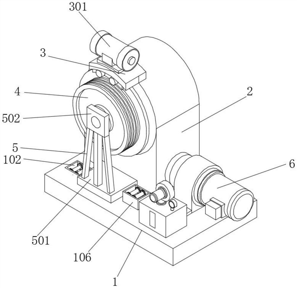
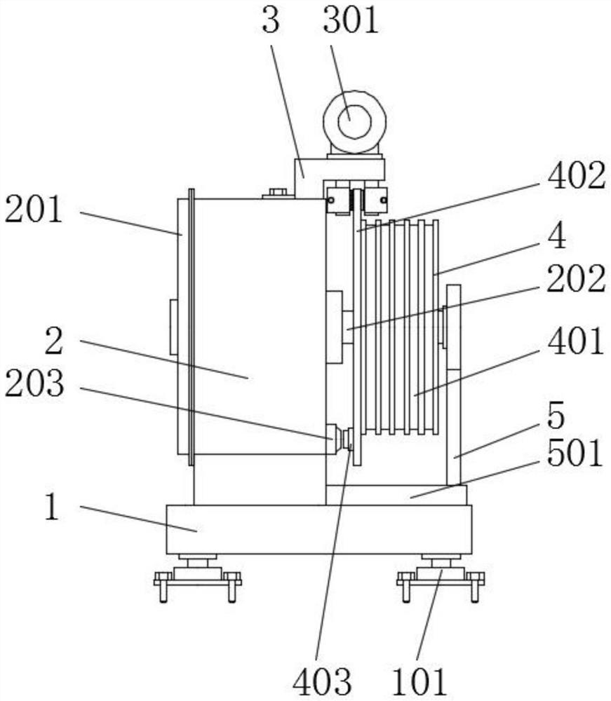
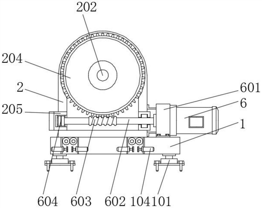
[0042] Embodiment 1 includes a support platform 1, the bottom of the support platform 1 is equipped with a support base 101 through bolts, and the worker fixes the bolts through the support base 101 on the ground to fix the support base 101, so that the support base 101 is convenient for the top. structure, the top of the support platform 1 is equipped with a fixed plate 501, the fixed plate 501 is installed on the front of the support platform 1, the inner side of the support platform 1 is equipped with a fixed ring 102, and the fixed ring 102 is located on the side of the fixed plate 501 On both sides, the inner side of the fixed ring 102 is movably equipped with a guide wheel 103, the inner side of the fixed ring 102 is equipped with a telescopic rod 104, and the telescopic rod 104 is located below the guide wheel 103, and one end of the telescopic rod 104 is installed with Brake plate 105, wherein a butt ring 106 is installed on the top of one group of fixed rings 102, and ...
Embodiment 2
[0044] Embodiment 2 includes a rotating rod 202, a driving wheel 4 is installed on the outside of the rotating rod 202, a guide groove 401 is provided on the outside of the driving wheel 4, a brake pad 402 is installed on the rear end of the driving wheel 4, and the braking An infrared generator 403 is installed on the back side of the sheet 402, and the infrared generator 403 corresponds to the infrared receiver 203. The rotation of the rotating rod 202 drives the driving wheel 4 at the front end to rotate, and the rotation of the driving wheel 4 drives the outer guide groove 401 to rotate, guiding The groove 401 limits the drive rope on the inner side, and can drive the drive rope to move smoothly. During the rotation of the driving wheel 4, it drives the brake pad 402 at the rear end to rotate, and the rotation of the brake pad 402 drives the infrared generator 403 to perform circular motion. , the infrared generator 403 sends out infrared induction lines during the movement...
Embodiment 3
[0046] Embodiment 3 includes a box body 2, a support plate 3 is installed on the top of the box body 2 through bolts, a hydraulic press 301 is installed on the top of the support plate 3 through bolts, and a fixing seat 302 is installed on the bottom of the support plate 3, A hydraulic rod 303 is installed through the inner side of the fixed seat 302, and an anti-skid plate 304 is installed on one end of the hydraulic rod 303. The box body 2 is fixed to the support plate 3 to ensure the stability of the support plate 3, and the support plate 3 is convenient for the hydraulic machine 301 and the fixed seat. 302 is fixed, the hydraulic machine 301 runs and transmits the hydraulic oil to the inside of the hydraulic rod 303 through the connecting pipe, so that the hydraulic rod 303 is elongated, and the hydraulic rod 303 drives the brake pads 402 to move forward, and the two sets of brake pads 402 are tightly attached to the driving wheel The front and rear outer surfaces of the to...
PUM
 Abstract
Description
Claims
Application Information
 - R&D
- Intellectual Property
- Life Sciences
- Materials
- Tech Scout
- Unparalleled Data Quality
- Higher Quality Content
- 60% Fewer Hallucinations
Browse by: Latest US Patents, China's latest patents, Technical Efficacy Thesaurus, Application Domain, Technology Topic, Popular Technical Reports.
© 2025 PatSnap. All rights reserved.Legal|Privacy policy|Modern Slavery Act Transparency Statement|Sitemap|About US| Contact US: help@patsnap.com


