
Wind wheel, centrifugal fan and clothes drying equipment

A centrifugal fan and wind wheel technology, applied in mechanical equipment, machines/engines, liquid fuel engines, etc., can solve the problems of large pressure loss, large dynamic noise, etc., to reduce the reverse pressure gradient, reduce pressure loss, and reduce aerodynamic noise Effect

Pending Publication Date: 2022-03-01
WUXI LITTLE SWAN ELECTRIC CO LTD
View PDF9 Cites 0 Cited by
  • Summary
  • Abstract
  • Description
  • Claims
  • Application Information

AI Technical Summary

Problems solved by technology

In related technologies, the blades of the wind rotor are mainly designed with equal thickness, that is to say, the thickness of the blades from the leading edge to the trailing edge is the same, resulting in a large pressure loss in the flow channel, which in turn generates a large aerodynamic noise

Method used


Image

  • Wind wheel, centrifugal fan and clothes drying equipment
  • Wind wheel, centrifugal fan and clothes drying equipment
  • Wind wheel, centrifugal fan and clothes drying equipment

Examples


Embodiment Construction

[0023] It should be noted that, in the case of no conflict, the embodiments in the application and the technical features in the embodiments can be combined with each other. Undue Limitation of This Application.

[0024] The orientations or positional relationships in the descriptions of the embodiments of the present application are based on the orientations or positional relationships shown in the accompanying drawings. It should not be construed as limiting the application to indicate that a device or element must have a particular orientation, be constructed, and operate in a particular orientation.

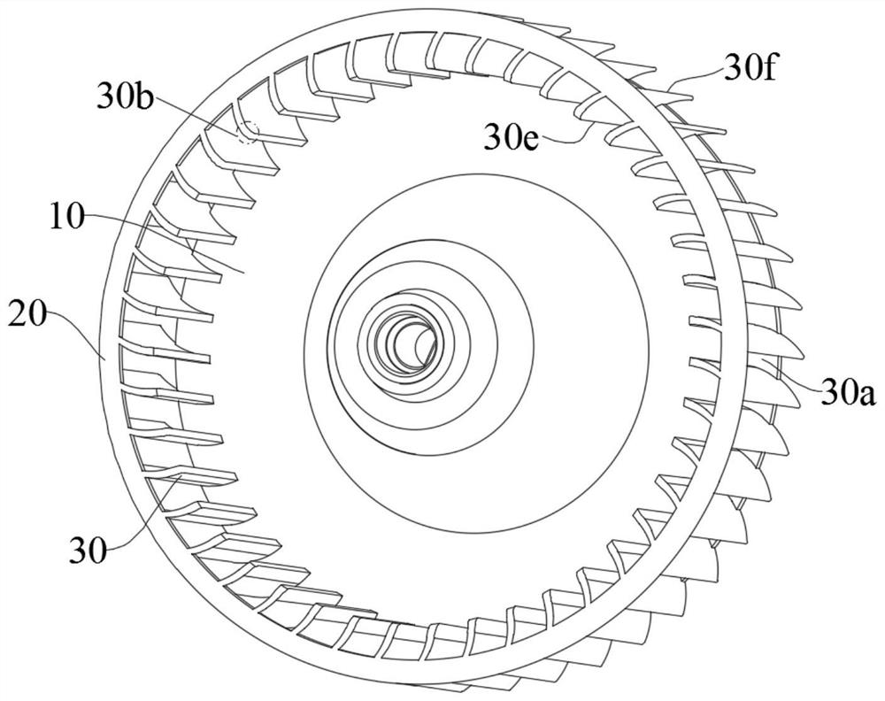
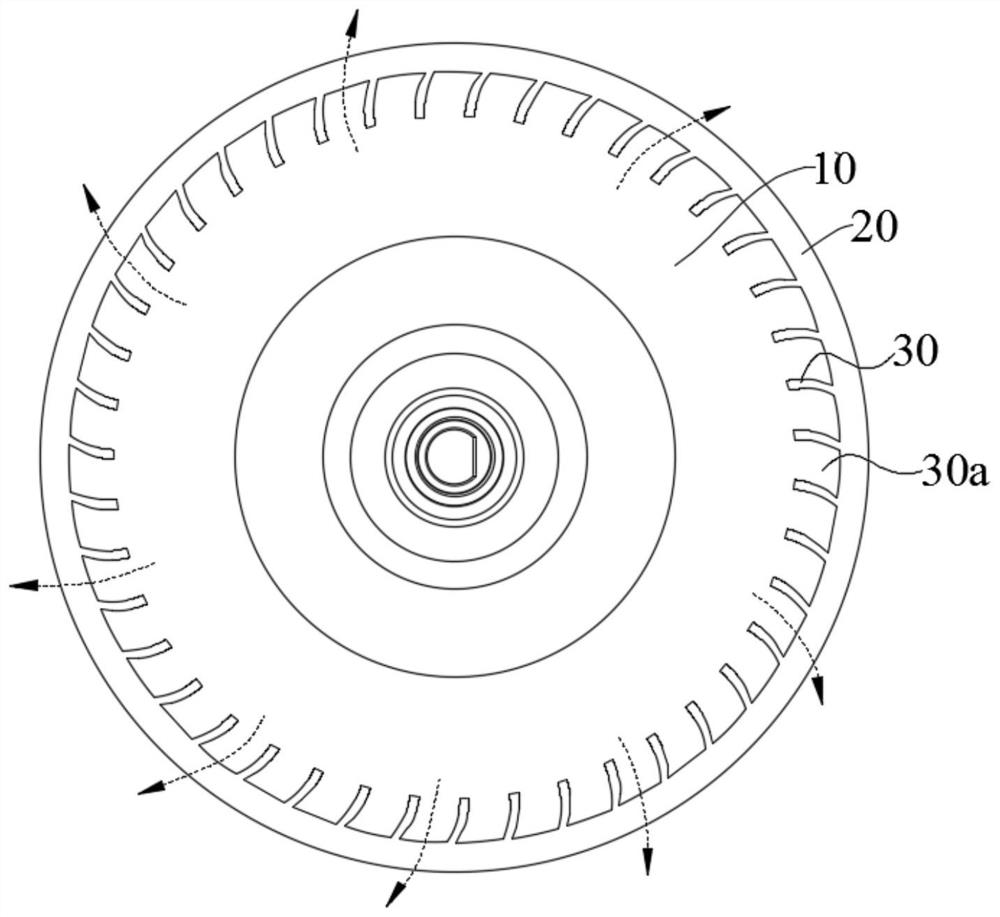
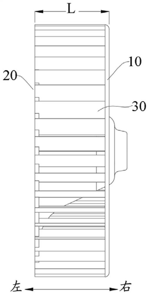
[0025] An embodiment of the present application provides a wind wheel for a centrifugal fan. see figure 1 , the wind wheel includes an end disk 10, a plurality of blades 30 arranged on one side of the end disk 10, and a plurality of blades 30 surround the rotation centerline of the wind wheel (simplified as Figure 4 with Figure 5 Point O in ) are arranged at intervals t...


PUM


Abstract

According to the wind wheel, the centrifugal fan and the clothes drying equipment, the wind wheel comprises the end disc and the multiple blades arranged on one side of the end disc, the multiple blades are arranged around the rotating center line of the wind wheel at intervals to form the annular structure, the end, away from the end disc, of the annular structure is the air inlet end, and the gap between every two adjacent blades is the air outlet channel; the thickness of the blade is gradually reduced in the direction from the front edge to the rear edge of the blade. According to the wind wheel, due to the fact that the thicknesses of the blades are gradually reduced, the circulation area of the air outlet channel is gradually increased in the airflow flowing direction, that is, the air outlet channel forms a diffusion air channel, and therefore the air speed in the air outlet channel can be reduced, the friction force between airflow and the surfaces of the blades can be reduced, and the pressure loss of the air outlet channel can be reduced; and the reverse pressure gradient in the air outlet channel is reduced, so that the possibility of flow separation generated at the rear edge of the blade is reduced, airflow energy loss is reduced, and aerodynamic noise is reduced.

Description

technical field [0001] The present application relates to the technical field of fans, in particular to a wind wheel, a centrifugal fan and clothes drying equipment. Background technique [0002] Taking the clothes dryer as an example, the aerodynamic noise caused by the rotation of the wind wheel is the main source of the noise of the clothes dryer, and the noise complaints caused by the wind wheel in the clothes dryer are also increasing day by day. In the related art, the blades of the wind rotor are mainly designed with equal thickness, that is to say, the thickness of the blades from the leading edge to the trailing edge is the same, which results in a large pressure loss in the flow channel, thereby generating relatively large aerodynamic noise. Contents of the invention [0003] In view of this, the embodiment of the present application expects to provide a wind wheel, a centrifugal fan, and a clothes drying device that reduce pressure loss and aerodynamic noise. ...

Claims


Application Information

Patent Timeline
Patent Type & Authority Applications(China)
IPC IPC(8): F04D29/30F04D29/66
CPCF04D29/30F04D29/666
Inventor 汪坤李磊谢邦明邓德喜宁喆
Owner WUXI LITTLE SWAN ELECTRIC CO LTD
Learn More