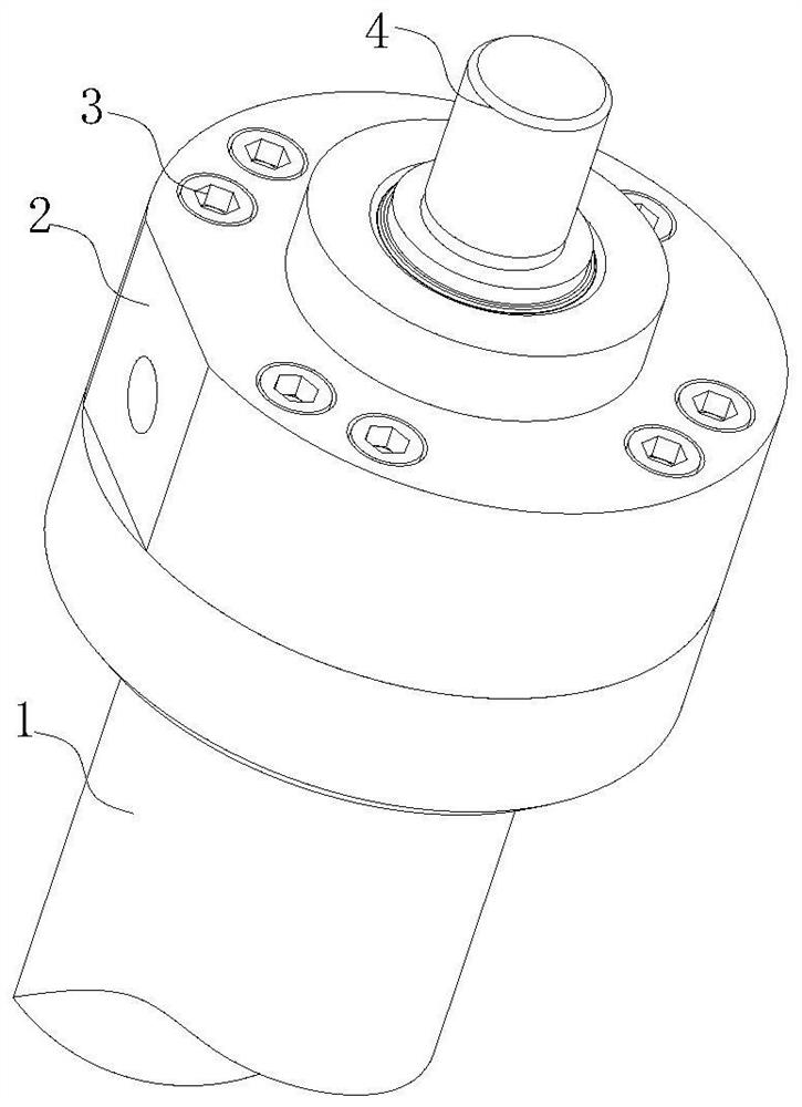
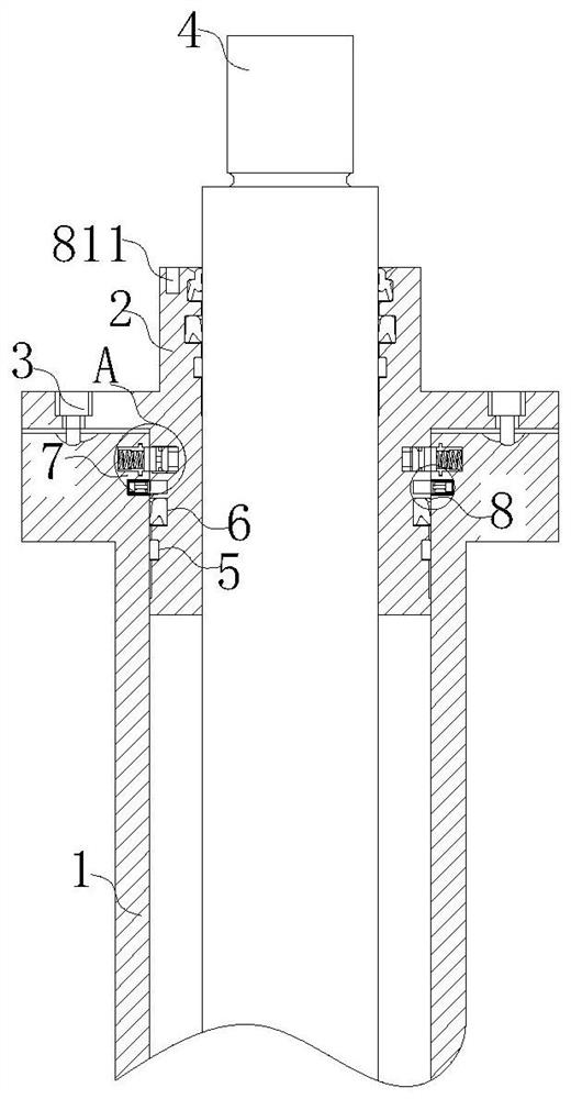
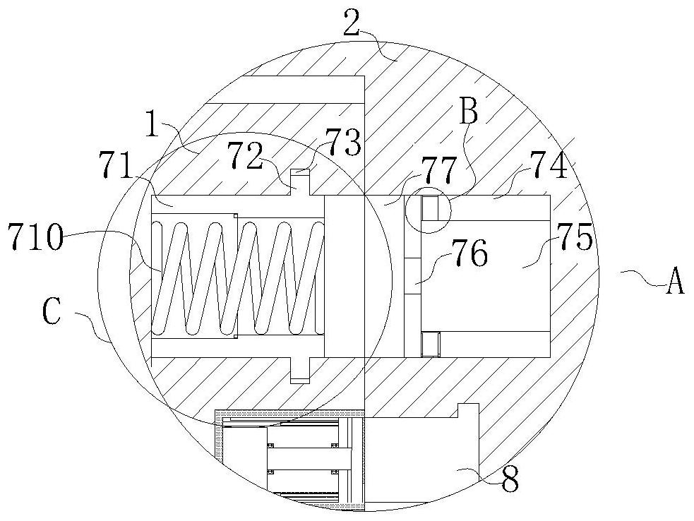
Connecting structure of hydraulic oil cylinder top cover and oil cylinder

A hydraulic cylinder and connection structure technology, which is applied to fluid pressure actuation devices, pipes/pipe joints/fittings, heat preservation, etc., can solve the problems of increasing the use cost, reducing the service life of the top cover, and high maintenance costs, so as to ensure the use Life, the effect of improving utility

Pending Publication Date: 2022-03-01
侯祖刚
View PDF1 Cites 2 Cited by
  • Summary
  • Abstract
  • Description
  • Claims
  • Application Information

AI Technical Summary

Problems solved by technology

[0004] Although the above comparative patents can make the installation and replacement of each seal more convenient and quick, and can realize automatic compensation after wear and tear, reduce the friction coefficient between each component, ensure the neutrality and anti-bias load ability are significantly enhanced, and effectively Wear and scratches are avoided, but the connection structure between the piston rod gland and the cylinder adopts a threaded connection, the joint surface between the gland and the cylinder is sealed with an O-ring, and the end of the cylinder is used for positioning, and the thread may become loose after repeated use In some cases, in order to prevent loosening, thread-locking glue is often used. However, after the internal sealing system of the oil cylinder is damaged, thread-locking glue is not easy to disassemble or may damage the thread or the surface of the joint after disassembly, resulting in high maintenance costs, and customers are more willing Buy a new hydraulic cylinder to replace the damaged hydraulic cylinder, but the purchase cycle limits the use of the equipment and increases the user's cost of use. At the same time, it is fixed with threaded holes and hexagon socket screws. If it is not discovered in time, the hydraulic oil will mix impurities due to the wear of the seal ring and the impurities contained in the hydraulic oil itself into the threaded connection between the cylinder and the cylinder top cover, which will cause the connection to be difficult to disassemble or damage the thread and the surface of the joint after disassembly, reducing the performance of the top cover. service life

Method used


Image

  • Connecting structure of hydraulic oil cylinder top cover and oil cylinder
  • Connecting structure of hydraulic oil cylinder top cover and oil cylinder
  • Connecting structure of hydraulic oil cylinder top cover and oil cylinder

Examples


Embodiment Construction

[0030] The following will clearly and completely describe the technical solutions in the embodiments of the present invention with reference to the accompanying drawings in the embodiments of the present invention. Obviously, the described embodiments are only some, not all, embodiments of the present invention. Based on the embodiments of the present invention, all other embodiments obtained by persons of ordinary skill in the art without making creative efforts belong to the protection scope of the present invention.

[0031] In describing the present invention, it is to be understood that the terms "center", "longitudinal", "transverse", "length", "width", "thickness", "upper", "lower", "front", " Back", "Left", "Right", "Straight", "Horizontal", "Top", "Bottom", "Inner", "Outer", "Clockwise", "Counterclockwise", etc. or The positional relationship is based on the orientation or positional relationship shown in the drawings, which is only for the convenience of describing t...


PUM


Abstract

The invention relates to the technical field of top cover and oil cylinder connecting structures, in particular to a hydraulic oil cylinder top cover and oil cylinder connecting structure which comprises an oil cylinder body, an oil cylinder top cover body is arranged on the outer surface of the upper end of the oil cylinder body, and inner hexagon screws which are evenly distributed are arranged on the outer surface of the upper end of the oil cylinder top cover body. The oil cylinder body is fixedly connected with the oil cylinder top cover body through an inner hexagon screw, and a movable rod is movably connected to the outer surface of the upper end of the oil cylinder top cover body in a penetrating and sealing mode. Through the arrangement of the first connecting groove, when oil starts to enter the oil cylinder body, due to the fact that the temperature of hydraulic oil is about 70 DEG C, substances such as carbon dioxide and air which are prone to expanding after being heated are contained in the first air bag, and the first air bag is made of a silicon rubber material, the problem that in the prior art, when thread loosening is solved through thread fixing and locking glue is avoided; and the problem that the screw thread or the surface of the combined part is possibly damaged after the screw thread or the combined part is disassembled is solved, and the overall practicability is improved.

Description

technical field [0001] The invention relates to the technical field of a connection structure between a top cover and an oil cylinder, in particular to a connection structure between a top cover and an oil cylinder of a hydraulic oil cylinder. Background technique [0002] The hydraulic cylinder is the actuator in the hydraulic transmission system. It is an energy conversion device that converts hydraulic energy into mechanical energy. It is used to drive the working mechanism to perform linear reciprocating motion or reciprocating swing. Hydraulic cylinders generally include cylinder barrels and piston rod assemblies. Piston rods The assembly includes a piston and a piston rod, wherein the piston is fixedly connected to the end of the piston rod, the outer peripheral surface of the piston is in sliding fit with the inner cavity of the cylinder, and the piston separates the inner cavity of the cylinder into a rod cavity and a rodless cavity, and One of the rod cavity or the ...

Claims


Application Information

Patent Timeline
Patent Type & Authority Applications(China)
IPC IPC(8): F15B15/14F15B15/20F16L59/04
CPCF15B15/1433F15B15/1438F15B15/1442F16L59/04
Inventor 侯祖刚吕豪杰
Owner 侯祖刚
Why Eureka
Try Eureka