Double-channel safety ignition mechanism and method

An ignition mechanism, dual-channel technology, applied in the direction of combustion ignition, combustion method, incandescent ignition, etc., can solve the problems of high failure rate, complex production process of DC motor, and high requirements for the use environment.

Active Publication Date: 2022-03-01
SHAANXI SPACEFLIGHT XINO MEILING ELECTRIC
View PDF27 Cites 0 Cited by
  • Summary
  • Abstract
  • Description
  • Claims
  • Application Information

AI Technical Summary

Problems solved by technology

However, the traditional dual-channel safety ignition mechanism is driven by a DC motor, and the separation and separation of the dual-channel channels is determined by the rotation of the DC motor. high failure rate

Method used


Image

  • Double-channel safety ignition mechanism and method
  • Double-channel safety ignition mechanism and method
  • Double-channel safety ignition mechanism and method

Examples


no. 1 approach

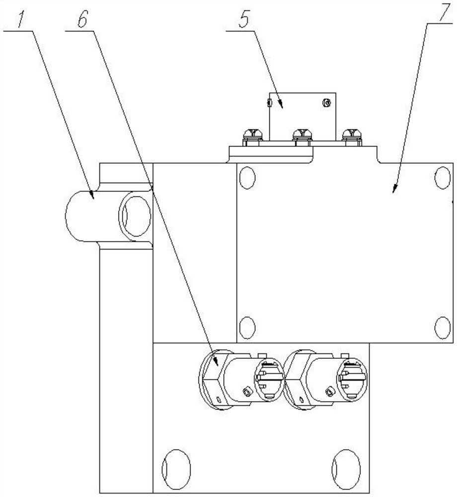
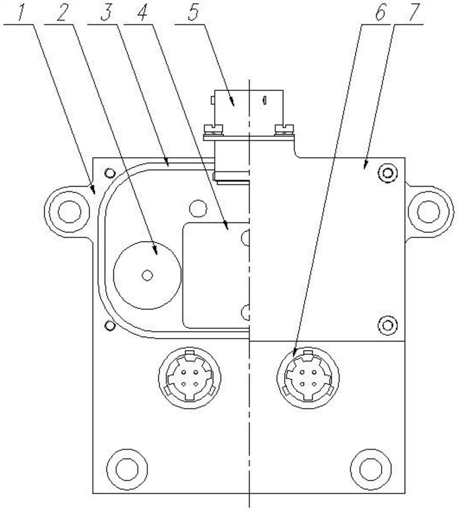
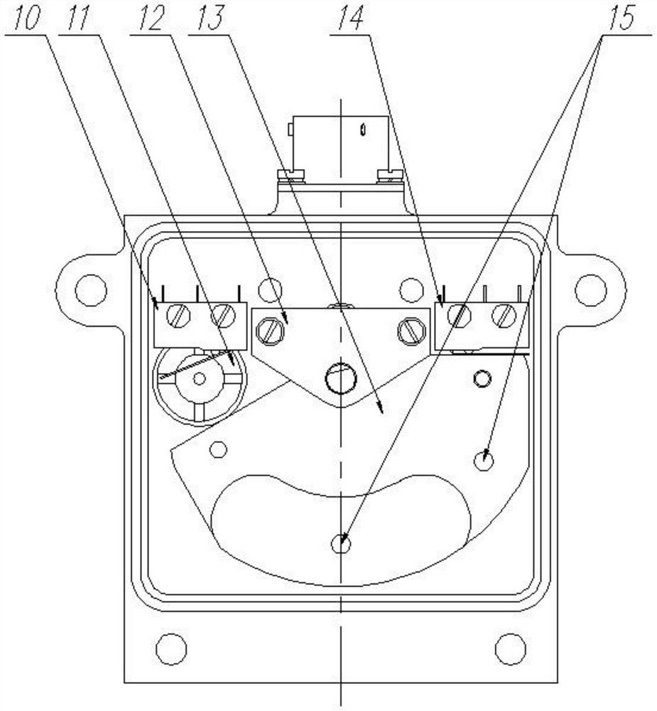
[0031] The first embodiment of the present invention relates to a dual-channel safety ignition mechanism, such as figure 1 As shown, the mounting base 1 is included, and the seat body of the mounting base 1 is provided with an aviation socket 5 for transmitting an ignition command and two electric igniters 6 for executing the ignition command, and a rotating electromagnet is also installed on the base body of the mounting base 1 4 (see figure 2 ), the output shaft of the rotating electromagnet 4 is sleeved with a rotating fan plate 13 that rotates synchronously with it, referring to image 3 and Figure 4 , Two fire holes 15 are provided on the rotating fan plate 13 .

[0032] The rotating electromagnet 4 drives the rotating fan plate 13 to rotate, so that the two fire holes 15 are respectively facing the two electric igniters 6 to form two fire receiving channels, or the closed surface of the rotating fan plate 13 covers two electric igniters. device 6, wherein the electr...

no. 2 approach

[0058] A dual-channel safe ignition method at least includes a dual-channel safe ignition mechanism, the dual-channel safe ignition mechanism has two states, namely a safe state and a working state, wherein the ignition method in the working state is as follows:

[0059] The unit tester sends an ignition command to the aviation socket 5, and the aviation socket 5 controls the two electromagnetic pins to be pulled out at the same time, and at the same time controls the rotation of the rotating electromagnet 4, the rotating fan plate 13 rotates and touches the working switch 10, and the unit tester controls the working electromagnetic pin 11 drop the pin, the pin shaft of the working electromagnetic pin 11 falls into the working pin hole 9 of the rotating fan plate 13, the rotating fan plate 13 stops rotating, and the two fire holes 15 of the rotating fan plate 13 are facing the two electric igniters 6 , forming two sets of fire channels.

[0060] The working principle of the du...


PUM


Abstract

The invention provides a double-channel safety ignition mechanism and method.The ignition mechanism comprises a mounting base, the mounting base is provided with an aviation socket used for transmitting an ignition instruction and two electric igniters used for executing the ignition instruction, the mounting base is further provided with a rotating electromagnet, and an output shaft of the rotating electromagnet is sleeved with a rotating sector plate; two fire passing holes are formed in the rotating sector plate; the rotating electromagnet drives the rotating sector plate to rotate, so that the two fire passing holes directly face the two electric igniters correspondingly to form two fire receiving channels, or the two electric igniters are covered with the closed plate face of the rotating sector plate. In the working state, fire can pass through the two sets of fire receiving channels to the lower-level fire receiving component, and even if one fire receiving channel breaks down, it can be guaranteed that the lower-level fire receiving component can be normally ignited; in a safe state, the two electric igniters are covered by the plate surfaces of the rotating sector plates, namely, the two sets of fire receiving channels are closed, and even if the electric igniters ignite due to unknown factors, the lower-level fire receiving component cannot be ignited due to the fact that the fire receiving channels are closed.

Description

technical field [0001] The invention belongs to the field of safety ignition, and in particular relates to a dual-channel safety ignition mechanism and method. Background technique [0002] In the field of safety ignition, the design concept of dual-channel safety ignition has been widely adopted. Dual-channel ignition can increase the success rate of ignition with a high probability and reduce failures such as ignition interruption caused by a channel failure. However, the traditional dual-channel safety ignition mechanism is driven by a DC motor, and the separation and separation of the dual-channel channels is determined by the rotation of the DC motor. The failure rate is high. Contents of the invention [0003] The purpose of the embodiments of the present invention is to provide a dual-channel safety ignition mechanism and method to overcome the above-mentioned technical defects. [0004] In order to solve the above-mentioned technical problems, the present invent...

Claims


Application Information

Patent Timeline
Patent Type & Authority Applications(China)
IPC IPC(8): F23Q7/00F23Q7/22F23Q7/24
CPCF23Q7/00F23Q7/22F23Q7/24
Inventor 张永强傅冬梅王茂森
Owner SHAANXI SPACEFLIGHT XINO MEILING ELECTRIC
Why Eureka
Try Eureka