Centering adjustment method for equipment output shaft and product input shaft

A technology of centering adjustment and output shaft, applied in the direction of using mechanical devices, measuring devices, instruments, etc., can solve problems such as complicated operation, and achieve the effect of simple calculation, clear principle and convenient operation

Pending Publication Date: 2022-03-01
HARBIN DONGAN ENGINE GRP
View PDF1 Cites 0 Cited by
  • Summary
  • Abstract
  • Description
  • Claims
  • Application Information

AI Technical Summary

Problems solved by technology

This alignment method is realized by mechanical cooperation with optical detection, which can achieve accurat

Method used


Image

  • Centering adjustment method for equipment output shaft and product input shaft

Examples


Example Embodiment

[0039] In order to further describe the content of the present invention, it is described below in conjunction with the schematic diagram,
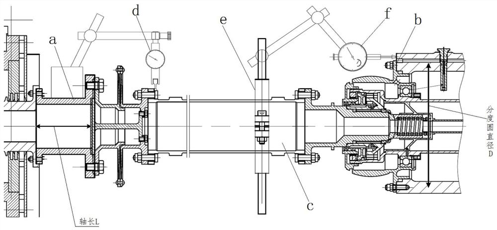
[0040] like figure 1 As shown, a, the output shaft of the high-speed gearbox, b, the seal mounting surface of the main reduction input shaft, c, the diaphragm-tooth coupling, d, the first dial indicator, e, the dial indicator bracket, f, the first dial indicator two-hundred-pointer,

[0041] When implementing the centering and positioning, the above-mentioned centering auxiliary mechanism is installed, wherein the fixed end of the base of the first dial indicator d is fixed at the output shaft a of the high-speed gearbox; the head of the first dial indicator d is in contact with the At the end face of the diaphragm shaft, the dial indicator bracket e is installed at the diaphragm-tooth coupling c, and the dial indicator bracket e is connected with the second dial indicator f; the head of the second dial indicator f is in contact with the...


PUM


Abstract

The invention relates to a centering adjustment method for an equipment output shaft and a product input shaft. The centering adjustment method is used for rapid centering adjustment of a main speed reducer input shaft and a high-speed gearbox connecting shaft. An adopted centering tool comprises a first dial indicator and a second dial indicator. During installation, the gauge stand fixing end of the first dial gauge is fixed on the output shaft of the high-speed gearbox, the gauge head of the first dial gauge is in contact with the end face of the diaphragm disc shaft, the second dial gauge is installed on the diaphragm disc-gear coupling through a support, and the gauge head of the second dial gauge is in contact with the sealing installation face of the main reduction input shaft. Wherein the gauge head of the second dial indicator and the gauge head of the first dial indicator are located on the same plane and are perpendicular to each other. And theoretical basis and guidance are provided for adjusting the angular deviation of the input shaft of the main speed reducer and the output shaft of the high-speed gearbox of the test bed to a reasonable range by calculating the angular deviation of the input shaft of the main speed reducer and the output shaft of the high-speed gearbox of the test bed.

Description

technical field [0001] The invention relates to a high-speed shaft centering calculation method, which is used for fast centering of an input shaft of a final reducer and a connecting shaft of a high-speed gearbox. Background technique [0002] At present, many aviation products need to do a series of tests before delivery or after repairs to ensure the use requirements of the products. For the main reducer of the aviation transmission system, according to the requirements of product assembly, before the test, the angular deviation between the input shaft of the main reducer and the output shaft of the high-speed gearbox of the test bench should be less than 4′. The tools and methods used for alignment The requirements are relatively high; among the currently published patents, such as patent CN109668530A, a method for detecting the centering of a shaft and a shaft hole and a centering detection device are proposed. The method for detecting the centering of a shaft and a sh...

Claims


Application Information

Patent Timeline
IPC IPC(8): G01B5/252G01D1/16
CPCG01B5/252G01D1/16
Inventor 赵天成阳开华杨阿饶程功赵志超万晓文蔡毅温艳陈洪喜商燕
Owner HARBIN DONGAN ENGINE GRP
Why Eureka
Try Eureka