Automatic digging device for medicinal material planting
An automatic and medicinal technology, which is applied in applications, excavators, digging harvesters, etc., can solve the problems of low operating efficiency and damage to medicinal materials by herbal claws, so as to reduce workload, facilitate herbal collection, and reduce the risk of medicinal material damage Effect
- Summary
- Abstract
- Description
- Claims
- Application Information
AI Technical Summary
Problems solved by technology
Method used
Image

Examples
Embodiment 1
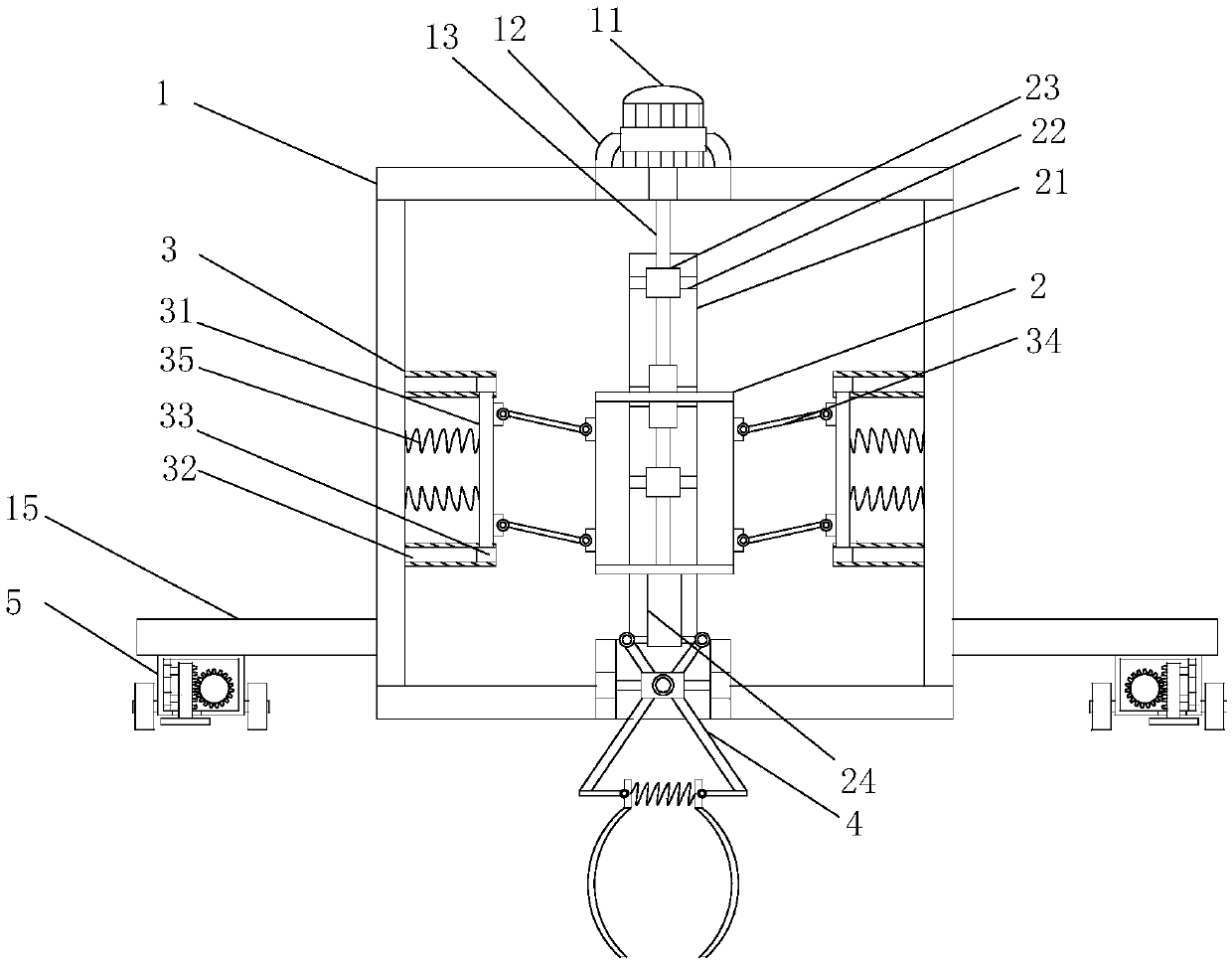
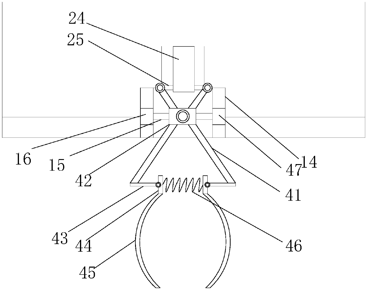
[0024] See figure 1 with figure 2 , An automatic digging device for planting medicinal materials, comprising a frame 1, an inner cavity of the frame 1 is provided with a transmission frame 2, and a transmission cylinder 21 is vertically installed on the transmission frame 2, and the transmission cylinder 21 is A fixed rod 22 is installed in the cavity, a transmission sleeve 23 is installed on the fixed rod 22, a threaded rod 13 is inserted into the transmission sleeve 23, and a motor frame 12 is installed on the top of the frame 1. A transmission motor 11 is installed on the screw rod 13 and the motor shaft of the transmission motor 11 is connected by a coupling. The bottom end of the transmission cylinder 21 is equipped with a push rod 24, and the bottom end of the push rod 24 is installed Support plate 25, the bottom end of the support plate 25 is connected with an excavating rack 4, the bottom of the frame 1 is provided with a limit slot 14, the excavating rack 4 is installe...
Embodiment 2
[0028] See figure 1 This embodiment is implemented as a further optimization. On the basis of it, movable frames 3 are installed on the left and right side walls of the transmission frame 2 respectively, and movable rods 31 are horizontally installed on the movable frames 3, and the movable rods Balls 33 are installed on the upper and lower ends of 31, and sliding grooves 32 are installed on the upper and lower side walls of the movable frame 3, and the balls 33 are respectively fitted into the corresponding sliding grooves 32. The movable rod 31 and the transmission frame A number of transmission connecting rods 34 are provided between 2 and the movable rod 31 is connected with a buffer spring 35, one end of the buffer spring 35 is connected to the movable rod 31, and the other end of the buffer spring 35 Connected with the side wall of the transmission frame 2.
[0029] For planting on sloping ground, the inclination angle of the transmission cylinder 21 can be adjusted appropr...
Embodiment 3
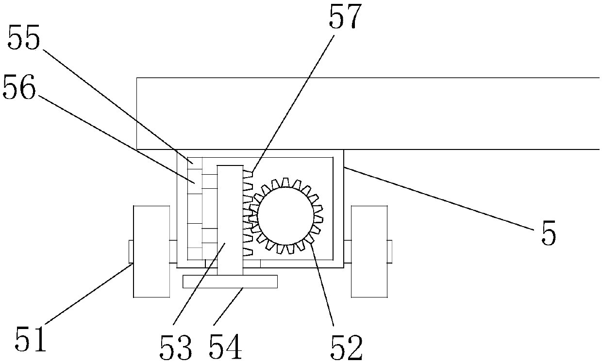
[0031] See figure 1 with image 3 This embodiment is a further optimization of the second embodiment. On the basis of this, a bottom plate 15 is installed at the bottom of the frame 1, and a roller seat 5 is installed at the bottom end of the bottom plate 15, and the roller seat 5 is horizontally installed with rollers. The roller shaft is equipped with a roller 51, the inner cavity of the roller seat 5 is provided with a transmission gear 52, the roller seat 5 is vertically pierced with a movable plate 53, and the bottom end of the movable plate 53 penetrates A fixed plate 54 is installed at the bottom of the roller seat 5, a rack 57 is installed on the movable plate 53, which meshes with the transmission gear 52, and a limit block 56 is installed on the side of the movable plate 53, so A limit rail 55 is installed on the side wall of the roller seat 5, and the limit block 56 is installed in the limit rail 55. A driving motor is installed on the rear side of the roller seat 5...
PUM
 Abstract
Description
Claims
Application Information
 - Generate Ideas
- Intellectual Property
- Life Sciences
- Materials
- Tech Scout
- Unparalleled Data Quality
- Higher Quality Content
- 60% Fewer Hallucinations
Browse by: Latest US Patents, China's latest patents, Technical Efficacy Thesaurus, Application Domain, Technology Topic, Popular Technical Reports.
© 2025 PatSnap. All rights reserved.Legal|Privacy policy|Modern Slavery Act Transparency Statement|Sitemap|About US| Contact US: help@patsnap.com