Photoelectric glass maintenance device and method

A technology of photoelectric glass and current detection device, which is applied in the direction of measuring devices, optical testing of defects/defects, and material analysis through optical means, which can solve the problem of low repair accuracy, false welding of lamp beads and lines, and affect the maintenance of photoelectric glass effect and other issues, to achieve the effect of improving accuracy and avoiding vibration

Inactive Publication Date: 2022-03-01
深圳御光新材料有限公司
View PDF0 Cites 0 Cited by
  • Summary
  • Abstract
  • Description
  • Claims
  • Application Information

AI Technical Summary

Problems solved by technology

[0004] However, in the production and manufacturing process of the existing photoelectric glass, it is necessary to connect multiple circuits on the circuit board with the lamp beads. At this time, it is necessary to solder the lamp beads and the circuits. In the fault, due to the improper process or operation, the lamp bead and the circuit are welded falsely, causing the lamp bead and the circuit to be in an unstable state of being connected and disconnected from time to time, so that in the fault of the photoelectric glass for lighting display, the inside of the photoelectric glass Irregular flickering of a certain lamp bead affects the overall aesthetics and image display effect of the photoelectric glass. Therefore, a laser welding machine is needed to perform fusion welding maintenance on the photoelectric glass
[0005] However, when the existing laser welding machine performs laser maintenance on the photoelectric glass, due to the vibration of the machine body, it is easy to slightly shift the position of the laser head and the virtual welding, resulting in a decrease in the accuracy of the repair and affecting the maintenance effect on the photoelectric glass. , and before the existing laser welding machine repairs the photoelectric glass, the staff needs to search and mark the position where the photoelectric glass is welded, and then put the photoelectric glass into the laser welding machine for laser welding, which is time-consuming and labor-intensive

Method used


Image

  • Photoelectric glass maintenance device and method
  • Photoelectric glass maintenance device and method
  • Photoelectric glass maintenance device and method

Examples


Embodiment

[0061] see Figure 1-13 middle,

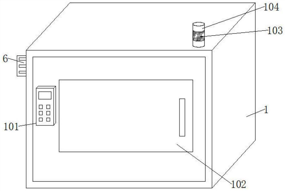
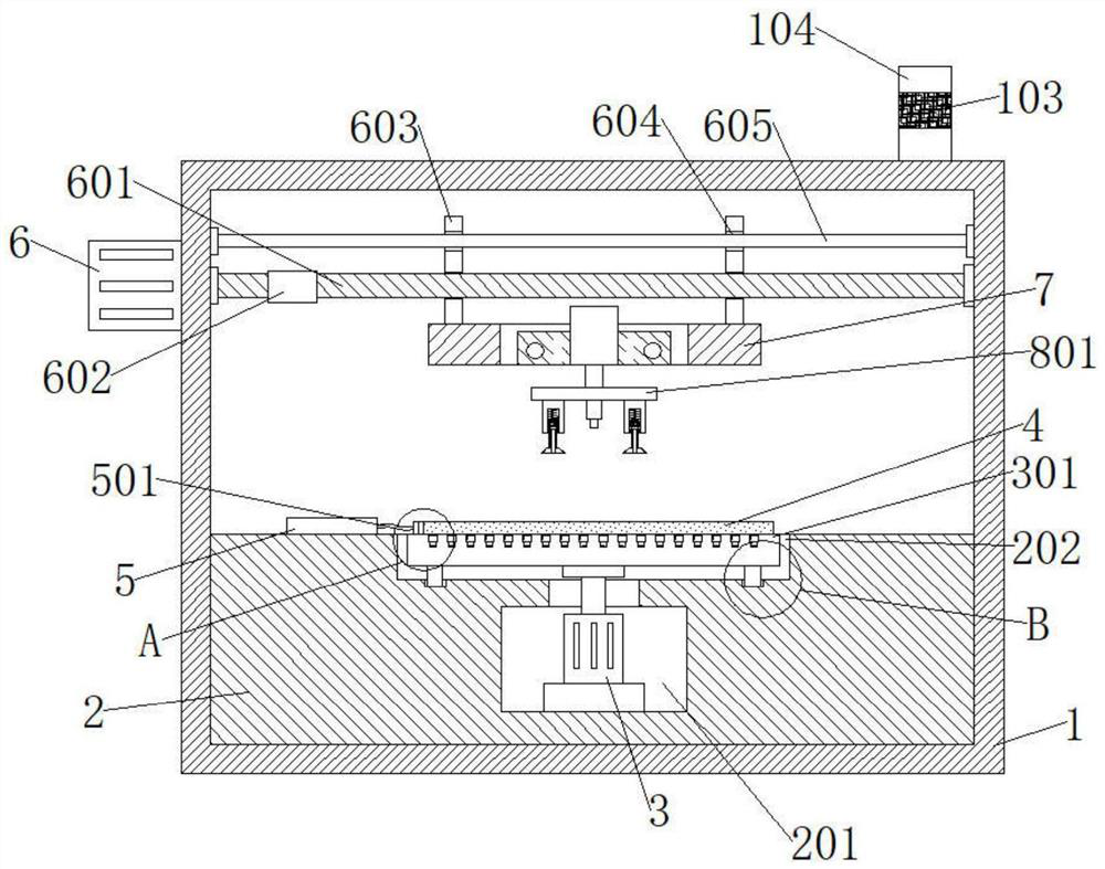
[0062] A maintenance device for photoelectric glass provided in this embodiment is fixedly installed on a body 1, and

[0063] The workbench 2 fixedly installed inside the body 1, the top of the workbench 2 is provided with a lifting plate 801, the top of the workbench 2 is provided with a placement groove 202, and the inside of the placement groove 202 is provided with a detection platform 301 for matching use;

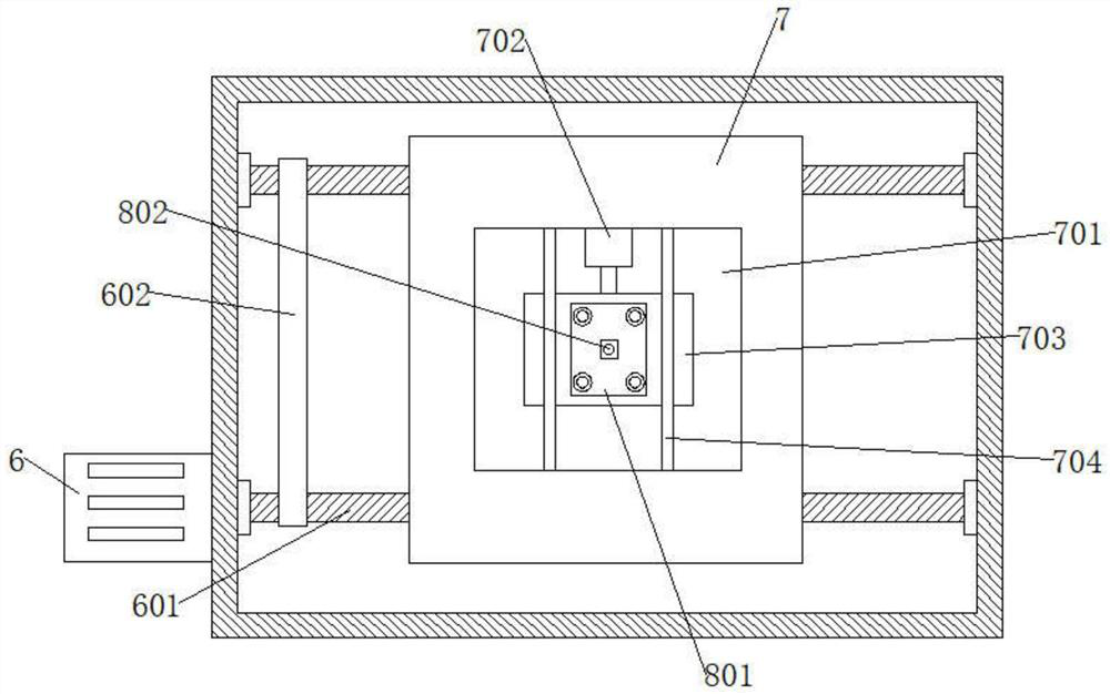
[0064] The photoelectric glass 4 placed on the top of the detection platform 301, the front of the body 1 is fixedly installed with the control panel 101, and the top of the lifting plate 801 is provided with a longitudinal moving plate 703;

[0065] The second electric push rod 8 fixedly installed on the top of the longitudinal moving plate 703, and the laser head 802 is fixedly installed at the bottom of the lifting plate 801;

[0066] A positioning component fixedly installed between the detection table 301 and the photoelectric...


PUM


Abstract

The invention provides a photoelectric glass maintenance device and method, and relates to the technical field of photoelectric glass, the photoelectric glass maintenance device comprises a machine body and a workbench fixedly mounted in the machine body, a lifting plate is arranged at the top of the workbench, a placement groove is formed in the top of the workbench, and a detection table matched with the placement groove for use is arranged in the placement groove; a control panel is fixedly installed on the front face of the machine body, a longitudinal moving plate and a second electric push rod are arranged on the top of the lifting plate, the second electric push rod is fixedly installed on the top of the longitudinal moving plate, and a laser head is fixedly installed at the bottom of the lifting plate. Through cooperative use of the fixing block, the reset spring, the connecting rod, the pull rod, the gear and the suction cup, the position of photoelectric glass can be fixed, the laser welding precision is improved, and through cooperative use of the current detection device, the power connection block, the circuit board, the photosensitive sensor and the positioning lamp, the pseudo soldering position can be marked and positioned.

Description

technical field [0001] The invention relates to the technical field of photoelectric glass, in particular to a maintenance device and method for photoelectric glass. Background technique [0002] Photoelectric glass is an organic combination of light energy, electric energy and glass. It can combine light source and power supply inside the glass, so as to achieve a more obvious display effect. It is widely used in various display areas, because photoelectric glass The color can be customized according to the requirements of customers, and its changes are quite diverse, which can have a very good advertising effect. [0003] According to the color of the lamp beads inside the photoelectric glass and the arrangement of the light-emitting time, different image displays are presented to achieve the effect of advertising display. [0004] However, in the production and manufacturing process of the existing photoelectric glass, it is necessary to connect multiple circuits on the ...

Claims


Application Information

Patent Timeline
Patent Type & Authority Applications(China)
IPC IPC(8): G01N21/01G01N21/95
CPCG01N21/01G01N21/95G01N2021/0112
Inventor 舒杨朱龙山
Owner 深圳御光新材料有限公司
Why Eureka
Try Eureka