Ultrahigh vacuum sample transfer cavity

An ultra-high vacuum and sample transfer technology, which is applied to the analysis of materials and instruments, can solve the problems of unavoidable open cavity sampling operation steps, complicated operation, and contaminated samples, and achieve the effect of simple structure, small volume, and pollution prevention

Pending Publication Date: 2022-03-01
国成仪器(常州)有限公司
View PDF0 Cites 2 Cited by
  • Summary
  • Abstract
  • Description
  • Claims
  • Application Information

AI Technical Summary

Problems solved by technology

However, most of the operations are complicated, and each method cannot avoid the operation step of "open cavity sampling", which exposes the sample to a non-vacuum gas environment
Once the vacuum environment around the sample is broken, the gas a

Method used


Image

  • Ultrahigh vacuum sample transfer cavity

Examples


Embodiment Construction

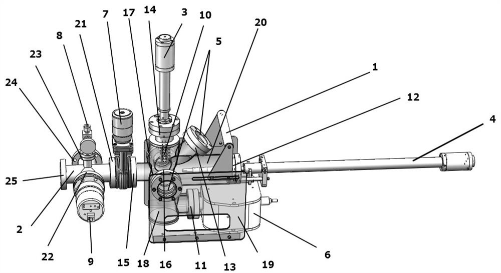
[0022] As shown in the figure, the present invention provides a portable device for transferring samples between different ultra-high vacuum systems.

[0023] figure 1 A perspective view of the overall structure according to an embodiment of the present invention is shown. In this embodiment, the sample transfer chamber consists of a transfer chamber 1, an auxiliary chamber 2, a sample transfer magnetic rod 3, a swing magnetic rod 4, an observation window 5, an ion pump 6, a gate valve 7, an air intake valve 8, and a vacuum gauge 9 1. The sample stage 10 is used to connect the ultra-high vacuum system for sample transfer. The ion pump 6 is in sealing connection with the first flange 11, the swinging magnetic rod 4 is in sealing connection with the second flange 12, the observation window 5 is in sealing connection with the third flange 13, the sixth flange 16, and the seventh flange 17. The sample magnetic rod 3 is in sealing connection with the fourth flange 14, the flapper...


PUM


Abstract

The invention discloses an ultrahigh vacuum sample transfer cavity which comprises a transfer cavity, an auxiliary cavity, a sample transfer magnetic rod, a swing magnetic rod, an observation window, an ion pump, a gate valve, an air inlet valve and a vacuum gauge. A vacuum flange capable of being in vacuum sealing connection with other devices is arranged on the outer side of the vacuum pipeline; five vacuum pipelines are welded to the auxiliary cavity, vacuum flanges capable of being in vacuum sealing connection with other devices are arranged on the outer sides of the vacuum pipelines, and the sample transfer magnetic rod, the swing magnetic rod, the observation window, the ion pump and the gate valve are connected with the transfer cavity; the other end of the gate valve is connected with an auxiliary cavity flange, and the vacuum gauge and the air inlet valve are connected with the auxiliary cavity flange. In this way, it can be guaranteed that the sample is always in the ultrahigh vacuum environment when transferred between the ultrahigh vacuum systems, the sample is prevented from being polluted by the outside, meanwhile, vacuum of equipment cannot be damaged, and operation is convenient.

Description

technical field [0001] The invention relates to an ultra-high vacuum instrument, in particular to an ultra-high vacuum sample transfer chamber. Background technique [0002] Generally speaking, the ultra-high vacuum equipment system is composed of vacuum pumps, vacuum gauges, vacuum chambers and other components with the help of vacuum pipelines according to certain requirements. To ensure that a specific vacuum environment is obtained and maintained in a certain space (typical vacuum degree is better than 1x10⁻⁹mbar), to ensure that a certain process or physical process is implemented in the vacuum system. Ultra-high vacuum systems are widely used in various research fields such as semiconductors, machining, physics, chemistry, materials and biological sciences. [0003] After the sample is prepared in the ultra-high vacuum system, in order to ensure its stable properties, it usually needs to be tested and analyzed in an environment that does not break the ultra-high vacuu...

Claims


Application Information

Patent Timeline
IPC IPC(8): G01N35/10
CPCG01N35/10
Inventor 董国材张祥梁枫
Owner 国成仪器(常州)有限公司
Why Eureka
Try Eureka