Flat self-supporting overhead composite optical cable based on skeleton optical cable

A composite optical cable and flat type technology, which is applied in the field of flat self-supporting overhead composite optical cable, can solve the complex process of urban road excavation application and approval process, affect the progress of the micro-pipe route acquisition project, and have no pre-buried air blowing micro-pipes in advance. and other problems, to achieve the effect of overhead laying, improving the ability to maintain shape, and simplifying the process of installation and construction

Pending Publication Date: 2022-03-01
YANGTZE OPTICAL FIBRE & CABLE CO LTD
View PDF11 Cites 3 Cited by
  • Summary
  • Abstract
  • Description
  • Claims
  • Application Information

AI Technical Summary

Problems solved by technology

However, at present, the underground pipeline resources in many places are seriously insufficient, and it is almost difficult to provide wiring space for the laying of air-blown micro-cables; moreover, in the planning and construction process of many cities, there are also situations where air-blown micro-pipes are not pre-buried in advance , resulting in air-blown micro-cables cannot be laid at all
In addition, with the gradual standardization of urban municipal construction, the application and approval process for urban pavement excavation has become more complicated, which further affects the acquisition of micro-pipelines and the progress of the project.

Method used


Image

  • Flat self-supporting overhead composite optical cable based on skeleton optical cable
  • Flat self-supporting overhead composite optical cable based on skeleton optical cable
  • Flat self-supporting overhead composite optical cable based on skeleton optical cable

Examples


Embodiment 1

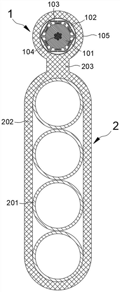
[0048] see figure 1 , the flat type self-supporting overhead composite optical fiber cable based on the skeleton optical cable in the preferred embodiment of the present invention includes a skeleton optical cable 1 and a flat microtube unit 2 .

[0049] Wherein, the skeleton optical cable 1 is arranged at one end of the micropipe unit 2, and the two are connected by a sheath transition zone 203, so that the skeleton optical cable 1 can become the load-bearing part of the composite optical cable, and can suspend and bear the entire optical cable. In actual setting, the end surfaces on both sides of the micropipe unit 2 are arranged vertically, and the skeleton optical cable 1 is connected and arranged on the top thereof.

[0050] Such as Figure 4 As shown in , the skeleton optical cable 1 in the preferred embodiment includes a skeleton 101. The skeleton 101 is preferably extruded from PE material, and a plurality of skeleton grooves 102 are spaced apart on its outer peripher...

Embodiment 2

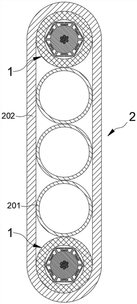
[0063] In this embodiment, the structure of the composite optical cable is as figure 2 As shown in , at this time, the skeleton optical cable 1 is arranged in the flat micropipe unit 2 , and preferably at least two micropipe units are distributed at both ends of the long axis of the micropipe unit 2 . At this time, at least one plastic microtube 201 is arranged between the two skeleton optical cables 1, and a flat structure is formed by combining the skeleton optical cables 1 and the plastic microtubes 201 arranged side by side. Round circular units.

[0064] In a preferred embodiment, the plastic microtubes 201 arranged between the two skeleton optical cables 1 are multiple arranged side by side, for example figure 2 The three shown in ; obviously, according to the needs of actual settings, the number of plastic microtubes 201 can be correspondingly optimized.

[0065] In Embodiment 2, the arrangement form of the skeleton optical cable 1 is preferably the same as that in ...

Embodiment 3

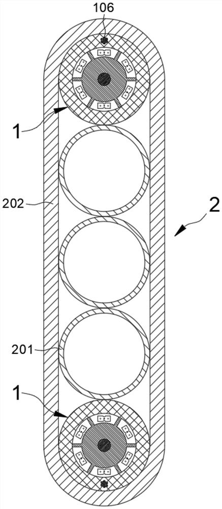
[0070] In this embodiment, the structure of the composite optical cable is as image 3 As shown in , it is not difficult to see that the biggest difference between the composite optical cable at this time and the composite optical cable in Embodiment 2 is that: in the first outer sheath 105 on the side where the two skeleton optical cables 1 are away from each other, there are respectively The reinforcement 106 makes the top and the bottom of the flat structure respectively form auxiliary reinforcement structures when it is suspended and erected.

[0071] In a preferred embodiment, the reinforcing member 106 is preferably a multi-core galvanized steel strand, such as image 3 shown in . However, according to the needs of actual settings, the reinforcing member 106 can also be set as a single-core galvanized steel wire, as long as it can meet the strength requirements of the actual application.

[0072] In more detail, on the basis of Embodiment 2 and Embodiment 3, it may be ...


PUM

PropertyMeasurementUnit
friction coefficientaaaaaaaaaa

Abstract

The invention discloses a flat self-supporting overhead composite optical cable based on a skeleton optical cable, and belongs to the technical field of communication optical cables, the skeleton optical cable and a flat microtube unit are compounded to form a self-supporting composite optical cable capable of being laid overhead, and the skeleton optical cable is used as a force bearing part of the composite optical cable. The plastic microtube in the microtube unit is used as a pipeline for subsequent optical cable air-blowing laying after overhead laying of the composite optical cable, overhead laying of the composite optical cable can be effectively achieved, and rapid air-blowing of newly-added optical cables after overhead laying of the composite optical cable is achieved. According to the flat self-supporting overhead composite optical cable based on the skeleton optical cable, overhead laying of the composite optical cable can be achieved, an air-blowing pipeline is reserved for air-blowing laying of a newly-added optical cable after the composite optical cable is installed, the construction and installation procedures of an initial optical cable and a newly-added expansion optical cable are simplified, the cost of subsequent expansion of the optical cable is reduced, and the construction efficiency is improved. Good application prospects and popularization values are realized.

Description

technical field [0001] The invention belongs to the technical field of communication optical cables, and in particular relates to a flat self-supporting overhead composite optical cable based on a skeleton optical cable. Background technique [0002] With the development of communication technology, people have higher and higher requirements for communication quality, and higher and higher requirements are also put forward for optical cables used in optical fiber communication. According to the different laying methods of optical cables, optical cables can be divided into pipeline optical cables, direct buried optical cables, aerial optical cables and underwater optical cables. [0003] Because it does not occupy the space above the ground and has little impact on the urban landscape, the existing urban optical cable laying methods often use pipeline optical cables, direct buried optical cables or underwater optical cables, and the application of overhead optical cables is r...

Claims


Application Information

Patent Timeline
Patent Type & Authority Applications(China)
IPC IPC(8): G02B6/44
CPCG02B6/4422G02B6/4404G02B6/4432G02B6/443G02B6/44384
Inventor 刘宏超胡海峰周力祁林杨向荣
Owner YANGTZE OPTICAL FIBRE & CABLE CO LTD
Why Eureka
Try Eureka