
Projection lens and projection system

A technology of projection lens and reflection system, applied in the field of projection display, can solve problems such as large deviation

Pending Publication Date: 2022-03-01
QINGDAO HISENSE LASER DISPLAY CO LTD
View PDF0 Cites 1 Cited by
  • Summary
  • Abstract
  • Description
  • Claims
  • Application Information

AI Technical Summary

Problems solved by technology

Two doublet lens groups are used to solve the problem of large color deviation of red, green and blue, and improve the quality of projection images

Method used


Image

  • Projection lens and projection system
  • Projection lens and projection system
  • Projection lens and projection system

Examples


Embodiment Construction

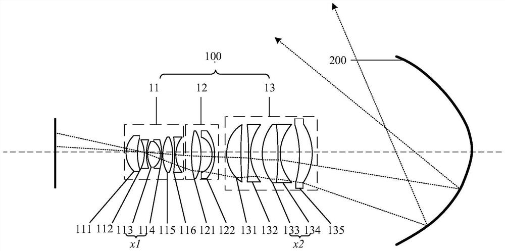
[0042]In order to make the above objects, features and advantages of the present invention more comprehensible, the present invention will be further described below in conjunction with the accompanying drawings and embodiments. Example embodiments may, however, be embodied in many forms and should not be construed as limited to the embodiments set forth herein; rather, these embodiments are provided so that this disclosure will be thorough and complete, and will fully convey the concept of example embodiments to those skilled in the art. The same reference numerals denote the same or similar structures in the drawings, and thus their repeated descriptions will be omitted. The words expressing position and direction described in the present invention are all described by taking the accompanying drawings as an example, but changes can also be made according to needs, and all changes are included in the protection scope of the present invention. The drawings of the present inve...


PUM


Abstract

The invention discloses a projection lens and a projection system. The projection system comprises a projection light source, a light valve modulation part and the projection lens. A light valve modulation part adopts a 4K high-resolution DMD (Digital Micromirror Device) of 0.66 '', so that large-size high-resolution display can be realized; the projection lens comprises a refraction system and a reflection system, the refraction system comprises a front lens group, a middle lens group and a rear lens group, the rear lens group comprises a doublet lens group, and the front lens group comprises a doublet lens group; the reflecting system comprises a reflecting mirror which is used for reflecting the imaging light of the refraction system. The problem of large deviation of red, green and blue colors is solved by adopting the two doublet lens groups, and the quality of a projection picture is improved. Wherein the doublet lens group in the rear lens group is mainly used for improving the spherical aberration of the lens in different spectrums and correcting the astigmatism of the lens; the doublet lens group in the front lens group is mainly used for correcting residual transverse chromatic aberration of the system.

Description

technical field [0001] The invention relates to the technical field of projection display, in particular to a projection lens and a projection system. Background technique [0002] Based on the digital light processing (Digital Light Processing, referred to as DLP) projection system, the light emitted by the light source is irradiated onto the digital micromirror device (Digital Micro Device, referred to as DMD) after modulation, and is reflected by the micromirror unit on the DMD. It is irradiated to the projection lens and projected onto the projection screen through the projection lens to form an image. [0003] At present, the DLP projection system usually adopts a telecentric optical path structure, which has good imaging quality, but a large rear working distance is required between the DMD and the projection lens to install the beam splitter, resulting in a larger overall volume of the projection system and occupying a larger area. Uses space while having a higher co...

Claims


Application Information

Patent Timeline
Patent Type & Authority Applications(China)
IPC IPC(8): G02B13/00G02B13/18G02B17/08G03B21/14
CPCG02B13/0045G02B13/0065G02B13/006G02B13/18G02B17/08G03B21/142
Inventor 陈陆阴亮
Owner QINGDAO HISENSE LASER DISPLAY CO LTD
Learn More