Portable special card issuing equipment
A convenient and card-issuing technology, applied in the directions of instruments, computer parts, transmission record carriers, etc., can solve the problems of inability to realize height adjustment related parts storage operation, inconvenient transportation, etc., to reduce the storage space, easy to carry, reduce The effect of squeezing friction
- Summary
- Abstract
- Description
- Claims
- Application Information
AI Technical Summary
Problems solved by technology
Method used
Image
Examples
Embodiment 1
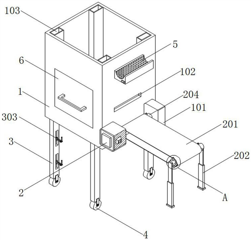
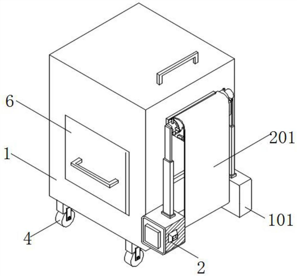
[0045] see figure 1 and Figure 5 , an embodiment provided by the present invention: a portable special-purpose card issuing device, including a housing 1 and a receiving and fitting groove 5, and the receiving and fitting groove 5 is installed on the front of the housing 1;
[0046] The top of the receiving fitting groove 5 is provided with an inwardly recessed arc-shaped groove 501, and one side outer wall of the receiving fitting groove 5 is equipped with a control switch 502 and a limit post 505, and the limit post 505 is located above the control switch 502, An electromagnet 503 is installed inside the receiving and fitting groove 5, and the electromagnet 503 is electrically connected to the control switch 502, and the other outer wall of the receiving and fitting groove 5 is installed with a restraining rope 504;
[0047] Specifically, the housing 1 can provide the necessary installation support space for the card issuing device, so that the card issuing operation can b...
Embodiment 2
[0050] see figure 1 , Figure 6 and Figure 7 , an embodiment provided by the present invention: a portable special-purpose card issuing device, including a housing 1 and a counting card issuing drawer 6, a counting card issuing drawer 6 is slidably installed on one side of the outer wall of the housing 1, and the front of the counting card issuing drawer 6 is open. Opening design, the inner wall of the counting card issuing drawer 6 is equipped with an L-shaped support frame 603 arranged equidistantly, and the inside of the counting card issuing drawer 6 is equipped with a hollowed-out card limiting frame 602 through the supporting plate frame 603, and the card limiting frame 602 The distance between the bottom and the bottom wall of the counting card-issuing drawer 6 is 0.8mm, and the bottom of the card limit frame 602 is equipped with a symmetrically arranged laser light 604, and the bottom wall of the counting card-issuing drawer 6 is embedded with a light-sensitive respo...
Embodiment 3
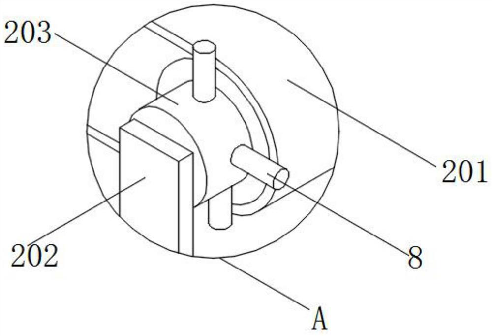
[0056] see figure 1 , image 3 and Figure 8 , an embodiment provided by the present invention: a portable special-purpose card issuing device, including a housing 1 and a restraint tube 8, a drive motor 2 and a support block 101 are installed on the front of the housing 1, and the support block 101 and the drive motor 2 are located at Below the fitting groove 5, the drive motor 2 and the support block 101 are symmetrically arranged. The surface of the support block 101 close to the drive motor 2 is equipped with a second shaft 204 through a bearing, and a conveyor belt 201 is installed on the surface of the second shaft 204. The first shaft 203 is installed inside the conveyor belt 201, the first shaft 203 and the second shaft 204 are connected through the transmission belt 201, and the surfaces of the first shaft 203 and the second shaft 204 are equipped with restraining tubes 8 equidistantly.
[0057] A pressure sensor 801 is installed on the inner wall of the constraint ...
PUM
| Property | Measurement | Unit |
|---|---|---|
| Thickness | aaaaa | aaaaa |
Abstract
Description
Claims
Application Information
 - R&D
- Intellectual Property
- Life Sciences
- Materials
- Tech Scout
- Unparalleled Data Quality
- Higher Quality Content
- 60% Fewer Hallucinations
Browse by: Latest US Patents, China's latest patents, Technical Efficacy Thesaurus, Application Domain, Technology Topic, Popular Technical Reports.
© 2025 PatSnap. All rights reserved.Legal|Privacy policy|Modern Slavery Act Transparency Statement|Sitemap|About US| Contact US: help@patsnap.com


