Radiation dose distribution prediction method and device based on CT image

A CT image and radiation dose technology, applied in the field of radiation dose distribution prediction methods and devices, to achieve the effect of improving accuracy and maintaining topology

Pending Publication Date: 2022-03-01
SHENZHEN YINO INTELLIGENCE TECH
View PDF0 Cites 0 Cited by
  • Summary
  • Abstract
  • Description
  • Claims
  • Application Information

AI Technical Summary

Problems solved by technology

However, the current CT image analysis technology has certain limitations, and it cannot accurately predict the radiation dose distribution based on CT images.

Method used


Image

  • Radiation dose distribution prediction method and device based on CT image
  • Radiation dose distribution prediction method and device based on CT image
  • Radiation dose distribution prediction method and device based on CT image

Examples


Embodiment 1

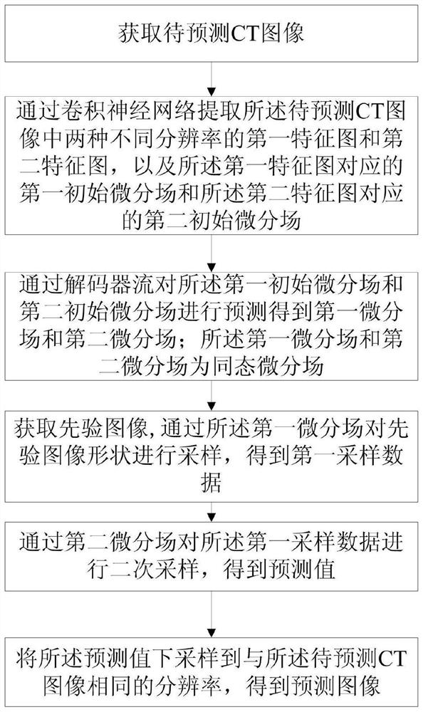
[0068] Please refer to figure 1 , a radiation dose distribution prediction method based on CT images, comprising steps:

[0069] S1. Obtain a CT image to be predicted;

[0070] S2. Extract the first feature map and the second feature map of two different resolutions in the CT image to be predicted through the convolutional neural network, and the first initial differential field and the second feature map corresponding to the first feature map The second initial differential field corresponding to the feature map;

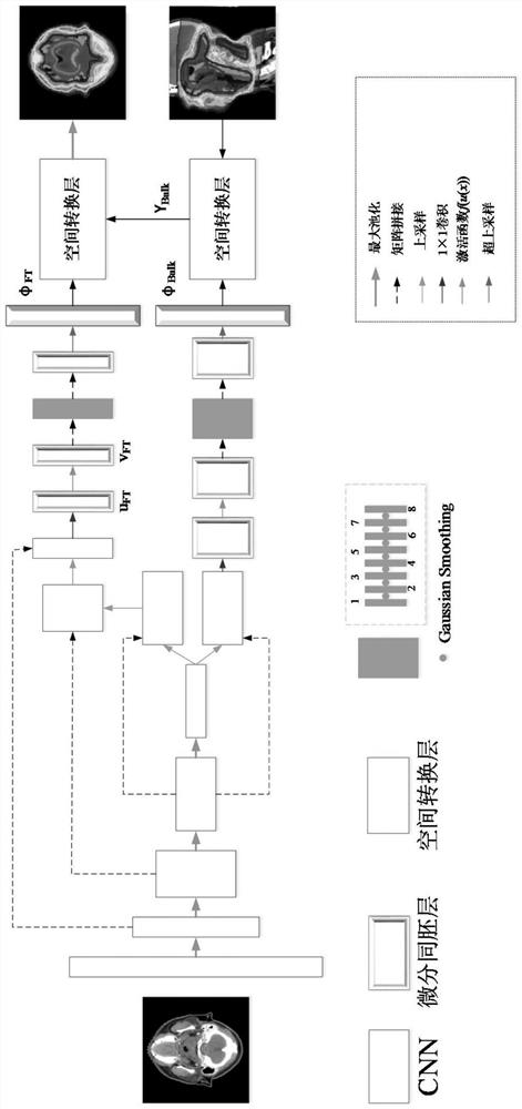
[0071] Among them, please refer to figure 2 , the convolutional neural network includes a first convolutional flow, a second convolutional flow and a third convolutional flow, the first convolutional flow is the convolutional neural network input to the CNN node at the branch, so The second convolution flow is the first CNN branch at the branch, and the second convolution flow is the second CNN branch at the branch; using a decoding branch structure similar to ...

Embodiment 2

[0089] The difference between this embodiment and Embodiment 1 is that a field regularization mechanism (Field Regularization) is also provided to supervise the loss of the training process;

[0090] specific:

[0091] Set the loss function: L=L Dice (Y 1 , Y label )+L Grad (φ FT )+L Grad (φ Bulk ), where L Dice is the dice loss function, Y 1 For the comparison sample, Y label is the predicted sample, that is, the predicted result, φ FT is the first differential field, φ Bulk is the second differential field, L Grad for:

[0092]

[0093] h and w are the parameters corresponding to the first feature map and the second feature map, that is, if calculating L Grad (φ FT ), bring in h and w corresponding to the first feature map, if calculate L Grad (φ Bulk ) is brought into h and w corresponding to the second feature map;

[0094] In an optional implementation manner, the loss function also includes a weighting parameter β;

[0095] Then L=L Dice (Y, Y label ...

Embodiment 3

[0097] Please refer to figure 2 , this embodiment provides a specific dose distribution prediction network framework structure;

[0098] The image input on the left is the CT image to be predicted as Y, the image input on the lower right is the prior image as P, and the image output on the upper right is the predicted value image as Y label ;

[0099] The first convolution flow includes five CNN nodes and four maximum pooling processes in turn; the bottleneck branch of the first convolution flow is the second convolution flow and the third convolution flow; the second convolution flow The second convolution flow is composed of a CNN node (upsampling block) and 1×1 convolution, and the third convolution flow is composed of three CNN nodes and 1×1 convolution; Matrix splicing is performed on corresponding CNN nodes in the first convolution flow to generate a two-dimensional field u, namely the first initial differential field and the second initial differential field;

[010...


PUM


Abstract

The invention discloses a radiation dose distribution prediction method and device based on a CT image, and the method comprises the steps: processing a to-be-predicted CT image through a convolutional neural network, and obtaining a first feature map and a second feature map which are corresponding to the to-be-predicted CT image and have different resolutions, and a first initial differential field and a second initial differential field; further predicting the feature map and the initial differential field through a decoder stream to obtain a first differential field and a second differential field, and continuously sampling a prior image shape through a continuous differential field, thereby deforming a prior with correct topological features through the continuous differential field to maintain topology; as the first differential field and the second differential field are differential homomorphic fields which are continuous deformation fields causing one-to-one mapping, the derivatives of the first differential field and the second differential field are reversible, and a positive Jacobian can be obtained, so that clear mapping between a prior shape and predicted image coordinates is given in dose registration, 100% topology maintenance is achieved, and the accuracy of dose registration is improved. And the accuracy of radiation dose distribution prediction is improved.

Description

technical field [0001] The invention relates to the field of CT image processing, in particular to a radiation dose distribution prediction method and device based on CT images. Background technique [0002] CT (Computed Tomography, computerized tomography) is widely used in clinical medicine because it can use precisely collimated X-ray beams, γ-rays, ultrasound and other rays for imaging, and has the characteristics of fast scanning time and clear images. Among them, especially in the field of clinical radiotherapy. Because the rays and radiation produced by radiotherapy are destructive not only to tumor tissue, but also to other organs and tissues, CT images are needed to determine the target area of ​​radiotherapy and radiation dose and other related treatment information. However, the current CT image analysis technology has certain limitations, and it cannot accurately predict the radiation dose distribution based on the CT image. Contents of the invention [0003]...

Claims


Application Information

Patent Timeline
Patent Type & Authority Applications(China)
IPC IPC(8): G06T7/00G06T3/40G06N3/04G06Q10/04G06V10/82
CPCG06T7/0012G06T3/4007G06Q10/04G06T2207/10081G06T2207/20084G06N3/045
Inventor 金晶梁军陈志坚李宁代智涛赵漫谢宝文王俊李建东
Owner SHENZHEN YINO INTELLIGENCE TECH
Why Eureka
Try Eureka