

Wave-shaped smoke tube structure of boiler
A technology for smoke pipes and boilers, which is applied to tubular elements, fluid heaters, heat exchange equipment, etc., can solve the problems of stagnant heat exchange efficiency of smoke pipes 15 and no research and development yet, and achieve the effect of effective transmission.
- Summary
- Abstract
- Description
- Claims
- Application Information
AI Technical Summary
Problems solved by technology
Method used
Image

Examples
Embodiment Construction
[0039] Hereinafter, the corrugated flue tube structure of the boiler according to the preferred embodiment of the present invention will be described in more detail with reference to the accompanying drawings.
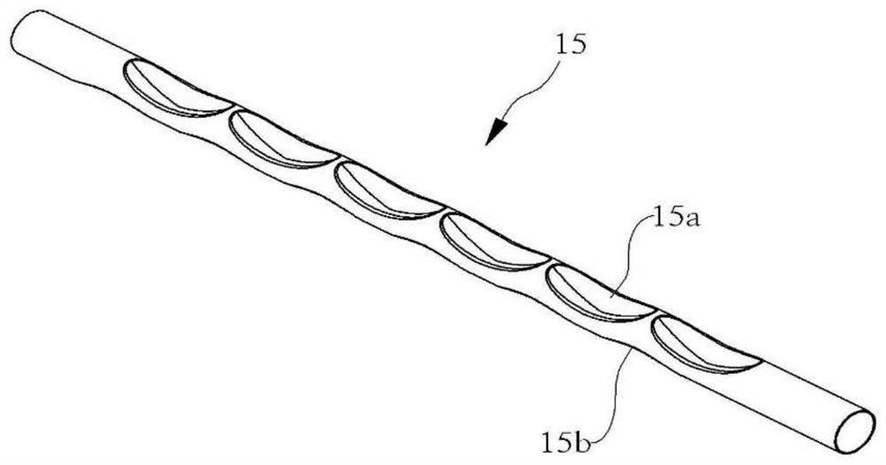
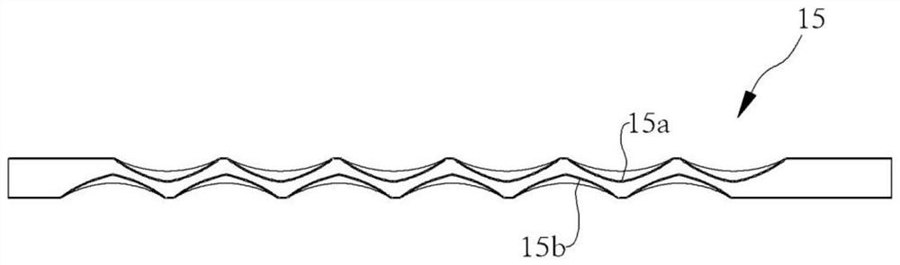
[0040] Figure 6 It is a perspective view schematically shown for illustrating the corrugated flue pipe structure of a boiler according to a preferred embodiment of the present invention, Figure 7 is showing Figure 6 Cutaway view of the A-A' section.
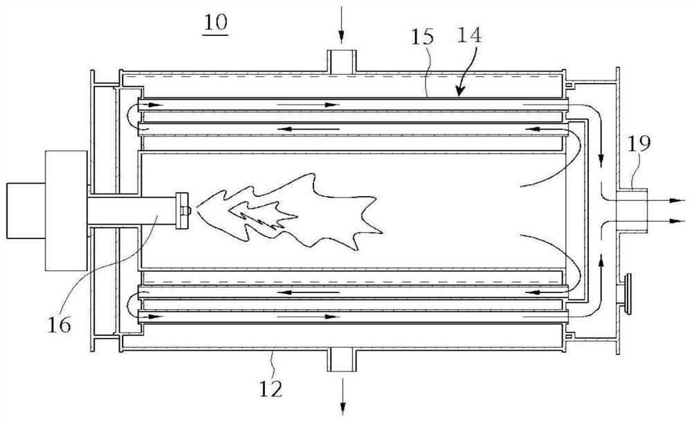
[0041] refer to Figure 6 and Figure 7 According to the preferred embodiment of the present invention, the corrugated smoke tube structure of the boiler includes a smoke tube 100 , and the smoke tube 100 includes a main body 110 , a first concave portion 120 , a second concave portion 122 , a blocking groove 130 and a concave end portion 140 .
[0042] The smoke pipe 100 is configured as a passage for moving the combustion gas generated by the burner of the boiler, and the external direct water supplied to the boi...
PUM
 Abstract
Description
Claims
Application Information