Powder laying control method, device and equipment and storage medium

A control method and powder coating technology, applied in the field of 3D printing, can solve the problems of processing efficiency, long waiting time, and increased workload, etc., and achieve the effect of improving processing efficiency and reducing the waiting time for powder coating.

Pending Publication Date: 2022-03-04
HANS LASER TECH IND GRP CO LTD +1
View PDF0 Cites 0 Cited by
  • Summary
  • Abstract
  • Description
  • Claims
  • Application Information

AI Technical Summary

Problems solved by technology

[0003] The above processing flow is relatively simple but not flexible enough
During the entire powder spreading process, the powder spreading shaft moves a complete back and forth, but only one time of powder spreading is completed. At the same time, the waiting time for powder spreading is long. For the processing of 3D printed parts with tens of thousands of layers, have a greater impact on processing efficiency
In addition, each powder spreading process will cause some powder to be wasted, and equipment operators need to frequently add powder to the powder supply tank, which increases the related workload
In the 3D printing industry that requires higher and higher processing efficiency, the existing powder coating process can no longer meet the actual production needs

Method used


Image

  • Powder laying control method, device and equipment and storage medium
  • Powder laying control method, device and equipment and storage medium
  • Powder laying control method, device and equipment and storage medium

Examples


Embodiment Construction

[0044] In order to make the object, technical solution and effect of the present invention more clear and definite, the present invention will be further described in detail below with reference to the accompanying drawings and examples. It should be understood that the specific embodiments described here are only used to explain the present invention, and are not used to limit the present invention, and the elements, structures and features in one embodiment can also be beneficially combined with other embodiments without further description. way.

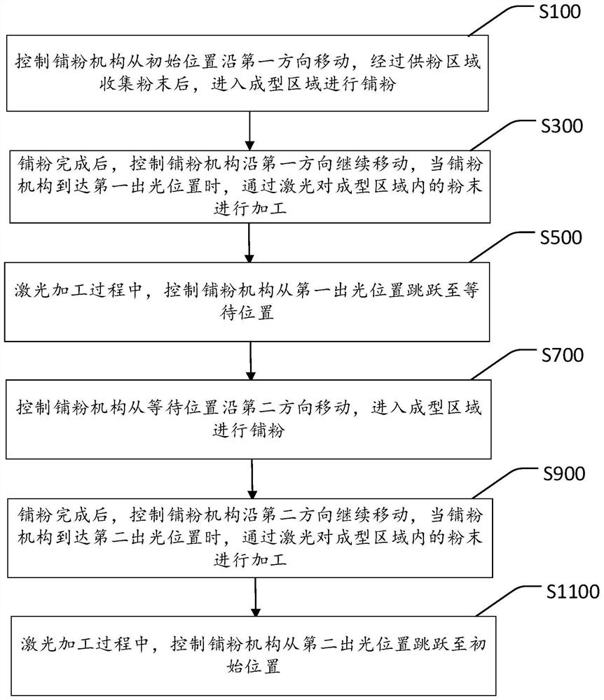
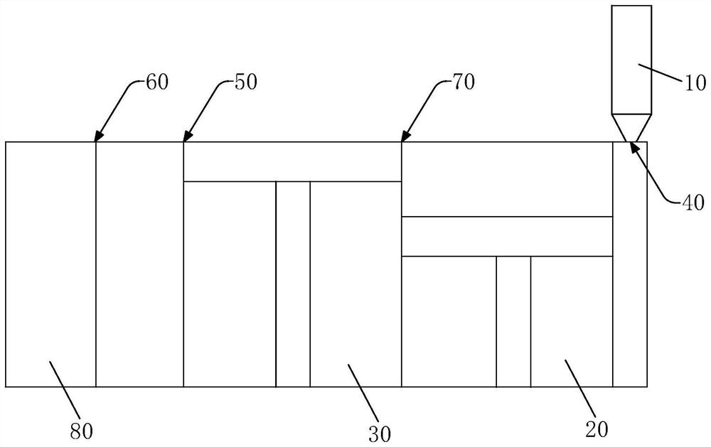
[0045] Please combine figure 1 and figure 2 , the powder spreading control method provided by the present invention includes a forward powder spreading step and a reverse powder spreading step, the powder can be transported back and forth, and enter the molding area 30 from both sides for powder spreading, thereby improving the powder spreading efficiency.

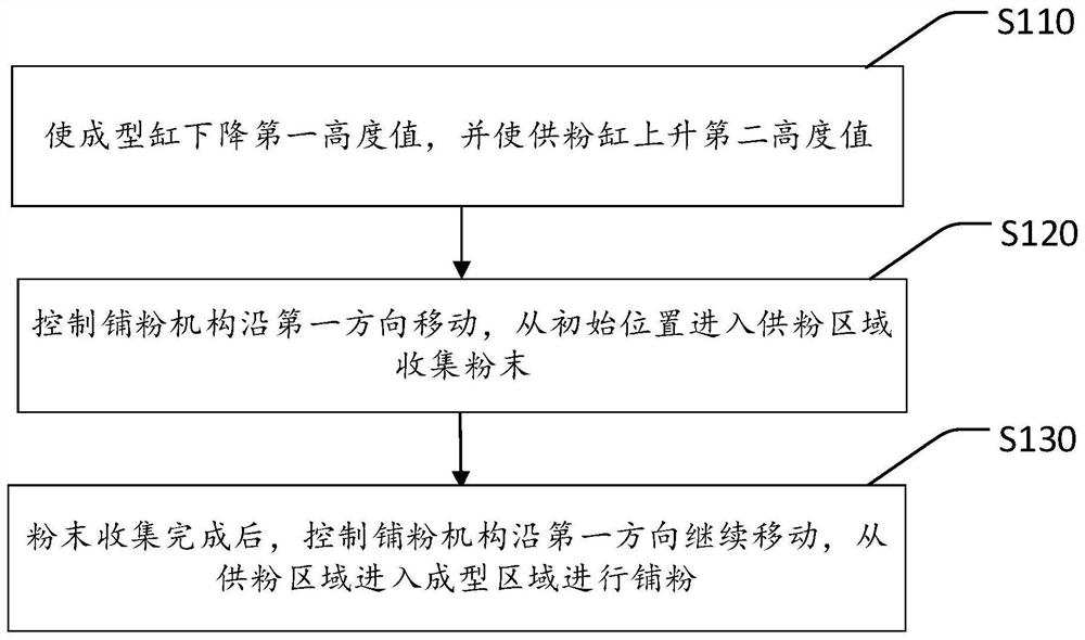
[0046] Wherein, the forward powder spreading step comprises:

[0047]...


PUM


Abstract

The invention discloses a powder laying control method, device and equipment and a storage medium, the powder laying control method comprises a forward powder laying step and a reverse powder laying step, in the forward powder laying step, when a powder laying mechanism reaches a first light emitting position, powder in a forming area is processed through laser, and the powder in the forming area is processed through a second light emitting position; meanwhile, the powder spreading mechanism is controlled to jump from the first light emitting position to the waiting position so as to carry out reverse powder spreading; in the reverse powder laying step, when the powder laying mechanism reaches the second light emitting position, the powder in the forming area is processed through laser, and meanwhile the powder laying mechanism is controlled to jump from the second light emitting position to the initial position so that forward powder laying can be conducted. On the basis of a single powder spreading area of the powder spreading equipment, two times of powder spreading actions can be realized after the powder spreading mechanism performs two times of complete full-stroke movement in the forward direction and the reverse direction, so that the powder spreading waiting time is shortened, and the printing efficiency of the equipment is further improved.

Description

technical field [0001] The invention relates to the technical field of 3D printing, in particular to a powder spreading control method, device, equipment and storage medium. Background technique [0002] The powder-spreading 3D printing equipment is usually composed of a powder-spreading structure, a forming cylinder and a powder-feeding cylinder. The processing process is to wait for the laser to pass through the galvanometer to complete the path scanning, and the powder-spreading shaft drives the scraper to move from the side of the powder supply cylinder to the forming machine. At one end of the cylinder, the powder in the powder supply cylinder is spread on the processing surface, and the excess powder is pushed into the recovery tank, and then the powder spreading shaft drives the scraper to return to the powder supply cylinder to start the powder spreading origin again, waiting for the next powder spreading action. [0003] The above processing flow is relatively simp...

Claims


Application Information

Patent Timeline
IPC IPC(8): B22F10/28B22F12/50B22F10/85B22F10/37B22F12/90B33Y10/00B33Y30/00
CPCB22F10/28B22F12/50B22F10/85B22F10/37B22F12/90B33Y10/00B33Y30/00Y02P10/25
Inventor 罗建欣欧阳征定刘旭飞周桂兵高云峰
Owner HANS LASER TECH IND GRP CO LTD
Why Eureka
Try Eureka