
Multi-partition array type selective melting manufacturing equipment and process

A technology of selective melting and manufacturing equipment, which is applied in the direction of manufacturing tools, additive manufacturing, processing and manufacturing, etc., can solve the problems of long powder spreading time, high processing comprehensive cost, low processing efficiency, etc., achieve stable powder spreading effect and reduce waiting time , The effect of improving processing efficiency

Active Publication Date: 2020-06-12
UNIV OF SHANGHAI FOR SCI & TECH
View PDF9 Cites 3 Cited by
  • Summary
  • Abstract
  • Description
  • Claims
  • Application Information

AI Technical Summary

Problems solved by technology

[0007] The technical problem to be solved by the present invention is to overcome the deficiencies of the prior art and provide a multi-partition array selective melting manufacturing equipment and process to solve the problems of long powder spreading time, low processing efficiency and comprehensive processing in the existing 3D printing production. high cost problem

Method used


Image

  • Multi-partition array type selective melting manufacturing equipment and process
  • Multi-partition array type selective melting manufacturing equipment and process

Examples


Embodiment Construction

[0024] The present invention will be further described below in conjunction with the accompanying drawings and embodiments.

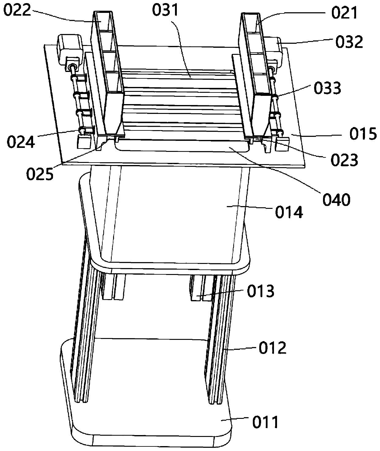
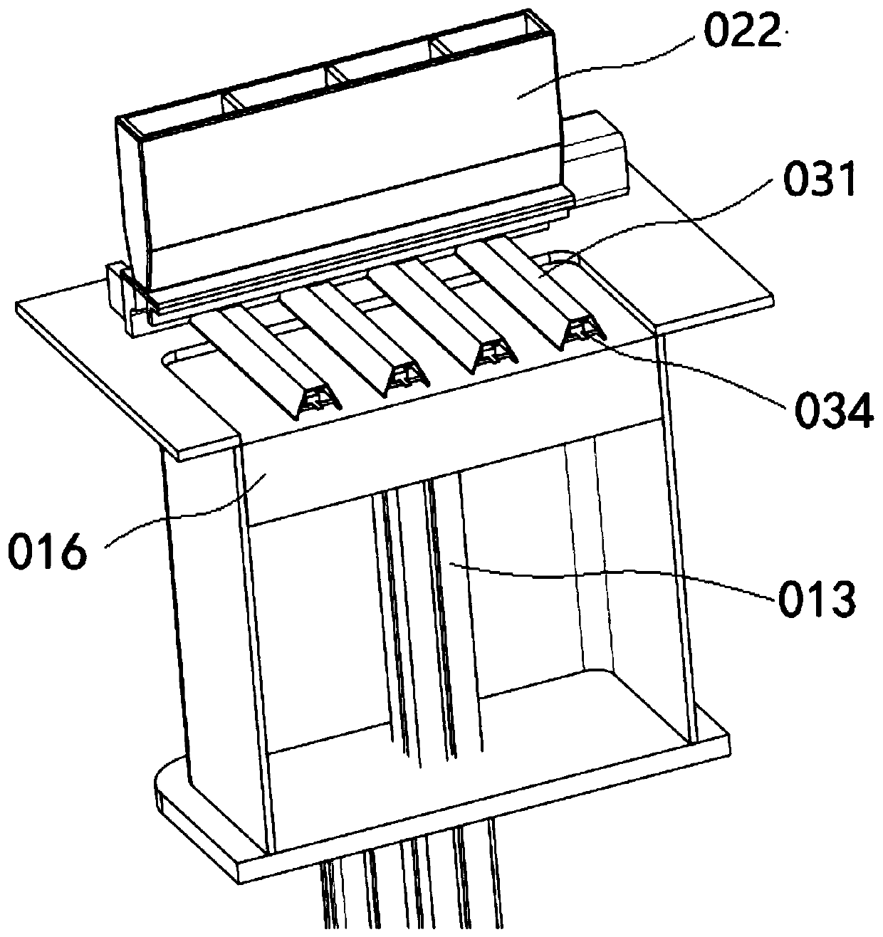
[0025] Such as figure 1 , as shown in 2, the multi-partition array type selective melting manufacturing equipment of the present invention includes a base 011, a support 012, a lifting guide rail 013, a forming bin 014, a forming platform 015, a forming base plate 016, a powder bin 1 021, and a powder bin 2 022, the first discharge port 023, the second discharge port 024, the sliding base of the silo 025, the powder spreading grid 031, the scraper drive motor 032, the scraper drive mechanism 033, the small scraper 034, and the powder forming area 040.

[0026] The base 011 in the equipment of the present invention is the basic load-bearing structure of the whole set of devices, ensuring that the whole device does not shake during operation, the support 012 is installed on the base 011, the forming chamber 014 is installed on the support 012, and the lif...


PUM


Abstract

The invention relates to multi-partition array type selective melting manufacturing equipment and a process. The equipment is characterized in that a forming bin is internally connected with a formingbottom plate through a lifting guide rail, a forming platform is arranged at the upper end of the forming bin, a plurality of powder laying grids which are distributed in parallel are arranged on theforming platform, a powder forming area on the forming platform is divided into a plurality of array type powder selecting areas, a powder bin is arranged at each of the two ends of each powder laying grid, the two ends of each powder laying grid and the powder bins on the corresponding powder laying grid are connected with the forming platform through bin sliding bases, the bin sliding bases drive the powder laying grids and the powder bins to perpendicularly reciprocate on the forming platform in the powder laying direction, multi-partition powder laying is formed, and high-energy beams canbe used for printing in the middles of the powder laying grids, so that powder laying and printing are relatively isolated; and a plurality of small scrapers are arranged in each powder laying grid,the small scrapers are connected with scraper driving motors through scraper driving mechanisms, and the scraper driving motors drive the small scrapers to reciprocate in the powder laying grids through the scraper driving mechanisms to evenly lay powder in the powder laying grids.

Description

technical field [0001] The invention relates to a metal and non-metal 3D printing manufacturing equipment, in particular to a multi-zone array type selective melting manufacturing equipment and process. Background technique [0002] Additive manufacturing, commonly known as 3D printing, is a combination of computer-aided design, material processing and forming technology, based on digital model files, through software and numerical control system, special metal materials, non-metal materials and medical biological materials, according to extrusion, Sintering, melting, light curing, spraying, etc. are accumulated layer by layer to create a manufacturing technology for physical objects. [0003] Among them, selective laser melting SLM (Selective Laser Melting), SLM technology is a technology that uses metal powder to be completely melted under the heat of a laser beam, cooled and solidified to form a shape. In order to completely melt the metal powder, the laser energy densit...

Claims


Application Information

Patent Timeline
Patent Type & Authority Applications(China)
IPC IPC(8): B29C64/153B29C64/20B29C64/214B22F3/105B33Y30/00B33Y10/00
CPCB29C64/153B29C64/20B29C64/214B33Y30/00B33Y10/00B22F10/00B22F12/30B22F10/28B22F12/67B22F12/224Y02P10/25
Inventor 曹志强沈爱萍
Owner UNIV OF SHANGHAI FOR SCI & TECH
Learn More