Eureka AIR delivers breakthrough ideas for toughest innovation challenges, trusted by R&D personnel around the world.

Rigidity-adjustable rear torsion beam suspension

A rigidity and torsion beam technology, applied in suspension, interconnection system, transportation and packaging, etc., can solve problems such as beam cracks, affecting the stability and safety of the whole vehicle, and high stress requirements on beams, so as to avoid deformation. Effect

Pending Publication Date: 2022-03-04
SICHUAN JIANAN IND
View PDF0 Cites 0 Cited by
  • Summary
  • Abstract
  • Description
  • Claims
  • Application Information

AI Technical Summary

Problems solved by technology

[0003] The torsion beam is the key component of the torsion beam semi-independent suspension, which plays the role of transmitting force, receiving force and connecting the two sides of the balance. When the car is driving on an uneven road, the torsion beam will bear a lot of force. When the deformation of the frame is unequal, the torsion beam will be twisted and deformed, which requires high stress on the beam. If the design is not good, it is easy to cause cracks or even breakage of the beam, which will affect the stability and safety of the vehicle.

Method used


Image

  • Rigidity-adjustable rear torsion beam suspension
  • Rigidity-adjustable rear torsion beam suspension
  • Rigidity-adjustable rear torsion beam suspension

Examples


Embodiment Construction

[0021] The present invention will be further described in detail below in conjunction with the accompanying drawings and specific embodiments.

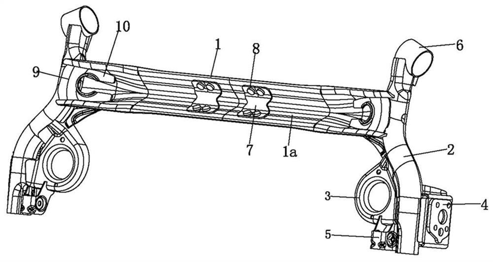
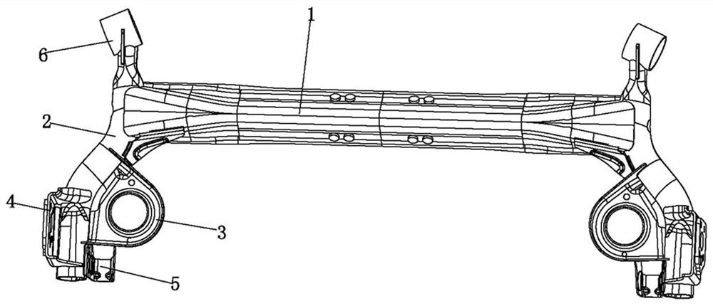
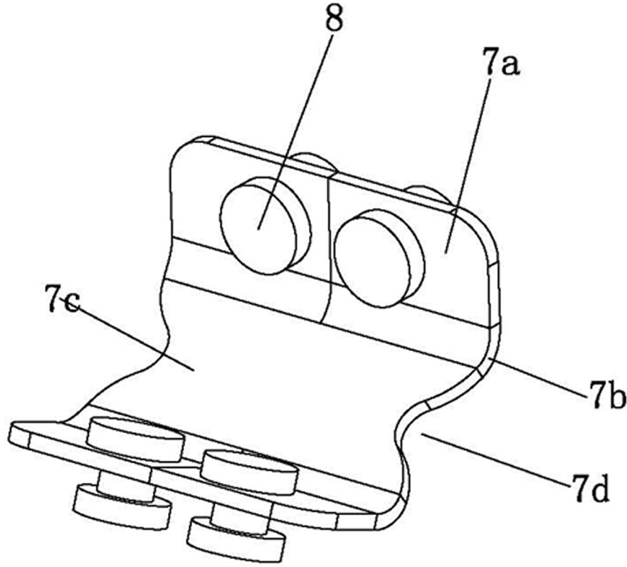
[0022] like Figure 1 to Figure 4 , the rear torsion beam suspension with stiffness adjustment of the present invention comprises a crossbeam 1, a longitudinal arm 2, a spring seat 3, a tire support 4, a shock absorber support 5, and a rear axle support 6, and the two ends of the crossbeam 1 are respectively fixed with The longitudinal arm 2 and the spring seat 3 are respectively fixed to the crossbeam 1 and the longitudinal arm 2, the tire support 4 is fixed to the longitudinal arm 2, the shock absorber support 5 is respectively fixed to the longitudinal arm 2 and the spring seat 3, and the rear axle support 6 is fixed to one end of the trailing arm 2,

[0023] Weld the prepared two longitudinal arm assemblies symmetrically to both ends of the finished beam 1, weld the spring seat 3 to the longitudinal arm assembly and the beam 1, a...


PUM


Abstract

The rigidity-adjustable rear torsion beam suspension comprises a cross beam, longitudinal arms, spring seats, tire supports, shock absorber supports and a rear axle body support, the longitudinal arms are fixed to the two ends of the cross beam respectively, the spring seats are fixed to the cross beam and the longitudinal arms respectively, the tire supports are fixed to the longitudinal arms, the shock absorber supports are fixed to the longitudinal arms and the spring seats respectively, and the rear axle body support is fixed to the rear axle body support. The rear axle body support is fixed at one end of the longitudinal arm, a groove extending in the axial direction of the cross beam is formed in the cross beam, a mounting hole is formed in the side wall face of the cross beam, the reinforcing component is located in the groove, at least one part of the reinforcing component is matched with the side wall face of the groove, and the reinforcing component and the cross beam are fixed into a whole through the fastener. The overall strength of the rear torsion beam suspension is improved by adjusting the rigidity of the cross beam.

Description

technical field [0001] The invention relates to the technical field of automobile rear torsion beam suspension, in particular to a rigidity-adjusted rear torsion beam suspension. Background technique [0002] The torsion beam semi-independent suspension is a commonly used car rear suspension structure at present. The trailing arms on the left and right sides are welded together by an integral V-shaped or U-shaped torsion beam, and the front end of the trailing arm is supported by rubber-metal. It is hingedly connected with the body, and connected with the wheel hub, shock absorber and spring at the rear end of the trailing arm. The longitudinal arm of the torsion beam can swing up and down around the rigid connection point so as to absorb the shock through the shock absorber and the shock absorption spring, and play the role of shock absorption. It has greater elasticity and can play the role of a horizontal stabilizer bar. Therefore, the torsion beam is the key component ...

Claims


Application Information

Patent Timeline
Patent Type & Authority Applications(China)
IPC IPC(8): B60G21/05
CPCB60G21/051B60G2200/21B60G2206/20
Inventor 胡礼宁晨曦陈海孙伟元曹敏向用均陈磊浦吕春肖强原磊
Owner SICHUAN JIANAN IND
Why Eureka
Eureka Blog
Learn More