
Pipe belt machine and broken belt capturing device thereof

A technology of a broken belt catching device and a pipe belt machine, which is applied to the conveyor control device, conveyor, conveyor objects, etc., can solve the problems of destroying the conveyor frame, low reliability, and large kinetic energy, and achieve engineering realization. Effective cost control, quick and accurate triggering, simple and reliable structure

Pending Publication Date: 2022-03-04
FUJIAN LONGKING +1
View PDF0 Cites 0 Cited by
  • Summary
  • Abstract
  • Description
  • Claims
  • Application Information

AI Technical Summary

Problems solved by technology

Due to the large transport volume and long distance, the backward slide of the material will continue to accelerate, and the kinetic energy is very huge. The material entrained by the conveyor belt will destroy the conveyor frame and damage the roadway, causing long-term production stoppage and major economic losses, and even affecting on-site work. personal safety of personnel
[0004] In order to solve this problem, the existing technology proposes to install a broken belt arresting device on the belt machine. This solution includes a catch mechanism and a trigger mechanism. The trigger mechanism includes a driving idler and a ratchet guide assembly. As a switch that triggers the torsion spring, the triggering force is small, and the upper roller often does not touch the tape, so there is a defect of low reliability

Method used


Image

  • Pipe belt machine and broken belt capturing device thereof
  • Pipe belt machine and broken belt capturing device thereof
  • Pipe belt machine and broken belt capturing device thereof

Examples


Embodiment Construction

[0034] In order to enable those skilled in the art to better understand the technical solutions of the present invention, the present invention will be further described in detail below in conjunction with the accompanying drawings and specific embodiments.

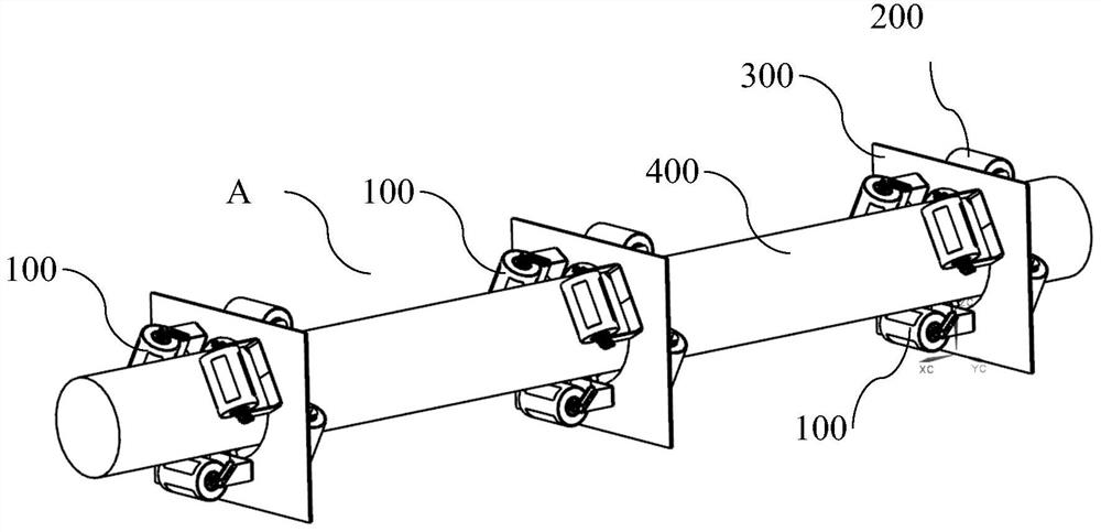
[0035] Without loss of generality, this embodiment takes the bracket 300 carrying the idler roller 200 of the belt machine shown in the figure as the basic fixed structure, and describes in detail the realization scheme of the broken belt arresting device proposed in this application. During the working process, the bracket 300 located in the loading section A or the return section B of the belt conveyor keeps the conveyor belt 400 in a cylindrical transport state through the loading idler roller 200 provided thereon. It should be understood that the specific functional structure of the carrier idler 200 is not the core invention point of the present application, and can be realized by those skilled in the art based on the...


PUM


Abstract

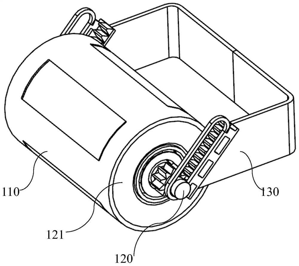
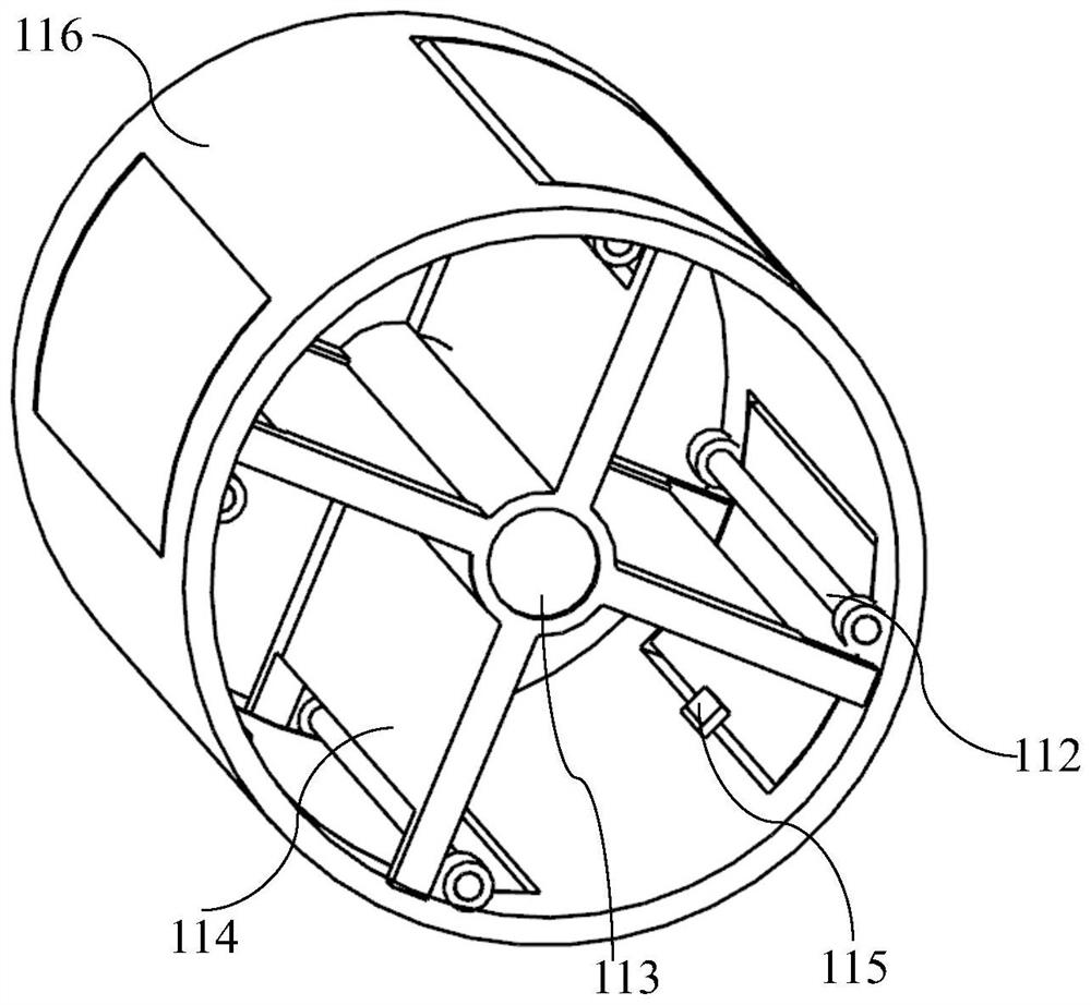
The invention discloses a pipe belt machine and a broken belt capturing device thereof, two sides of a support are respectively provided with an inclined rack, two side shaft ends of a carrier roller shaft are respectively and fixedly provided with a gear meshed and matched with the rack, and a carrier roller body is sleeved on the carrier roller shaft; the carrier roller body is provided with a plurality of overturning capturing pieces which are circumferentially arranged on a peripheral body at intervals, the carrier roller shaft and the carrier roller body can rotate synchronously in one direction, and the carrier roller shaft and the carrier roller body rotate asynchronously when the conveying belt moves forwards to drive the carrier roller body to rotate in the first direction; when the conveying belt moves reversely to drive the carrier roller body to rotate in the second direction, the carrier roller shaft and the carrier roller body rotate synchronously, the carrier roller shaft and the carrier roller body can be sequentially meshed along the racks through the gears and form the trend of tooth displacement towards the second ends of the gears, and the overturning capturing piece is located at the capturing working position. By means of the scheme, reliable capturing operation can be achieved through quick triggering when belt breakage accidents happen, and technical guarantee is provided for safe and reliable operation of a conveying system.

Description

technical field [0001] The invention relates to the technical field of material conveying, in particular to a pipe conveyor and a broken belt arresting device. Background technique [0002] At present, the tube belt conveyor has been widely used in electric power, metallurgy, port and other industries due to its good comprehensive conveying performance, and has a development trend of large-capacity and long-distance. As we all know, for the conveyor belt conveyor, the tension on the conveyor belt is very large during the material lifting process, and the motor needs to output a large torque to drive the conveyor to run normally. During the long-term continuous operation of the conveyor belt, fatigue damage or damage by foreign objects may occur, which may cause the conveyor belt to suddenly break during operation, which is called broken belt. [0003] When a belt break occurs, the conveyor belt will slide backwards at high speed with the material. Due to the large transpor...

Claims


Application Information

Patent Timeline
Patent Type & Authority Applications(China)
IPC IPC(8): B65G43/00B65G43/02B65G15/60
CPCB65G43/00B65G43/02B65G15/60
Inventor 廖辉苏金辉蓝武生彭锐丹卢小薇
Owner FUJIAN LONGKING
Learn More