[0023] The technical solutions in the embodiments of the present invention will be clearly and completely described below with reference to the accompanying drawings in the embodiments of the present invention. Obviously, the described embodiments are only a part of the embodiments of the present invention, but not all of the embodiments. Based on the embodiments of the present invention, all other embodiments obtained by those of ordinary skill in the art without creative efforts shall fall within the protection scope of the present invention.
[0024] In order to make the above objects, features and advantages of the present invention more clearly understood, the present invention will be described in further detail below with reference to the accompanying drawings and specific embodiments.
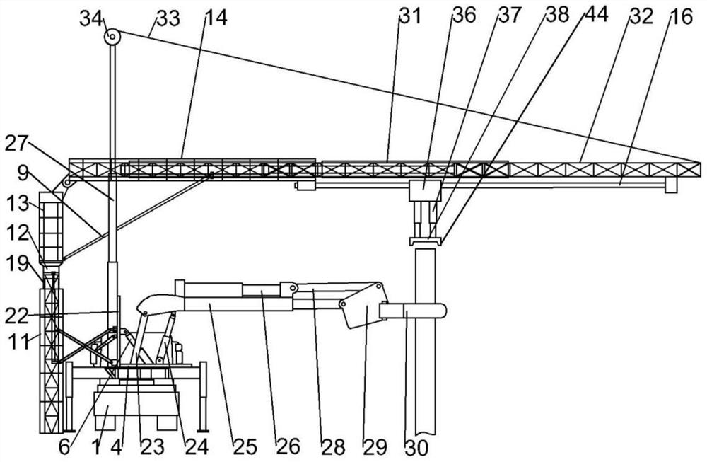
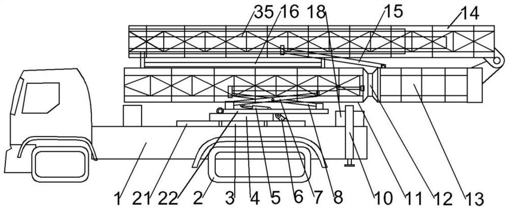
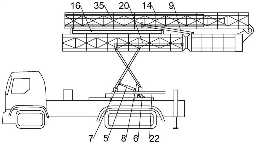
[0025] refer to Figure 1-6 As shown, the present invention provides a flood disaster relief pile planting device, comprising a vehicle body 1, one side of the vehicle body 1 is connected with a support frame assembly, the bottom of the support frame assembly is set on the ground, and the support frame assembly The telescopic end of the top extends to the top of the other side of the car body 1, and a drive assembly for planting piles is connected below the telescopic end. Below the assembly and corresponding to the drive assembly, the two sides of the car body 1 are vertically connected with hydraulic support columns 10 for stabilizing the car body 1, the top surface of the car body 1 is rotatably connected with a rotating platform 4, and the bottom end of the manipulator is detachable Connected to the top surface of the rotating platform 4 , the side of the support frame assembly close to the vehicle body 1 is connected to the rotating platform 4 , and the rotating platform 4 is rotatably connected to the top surface of the vehicle body 1 through the first stepping motor 3 .
[0026] The support frame assembly is arranged on the side of the vehicle body 1 away from the dike opening, and the hydraulic support columns 10 on both sides of the vehicle body 1 can be used to make the top of the support frame assembly telescopic during the process of lifting or grabbing the pile body. The pile body is hoisted steadily at the end to achieve the purpose of stable pile planting; on the one hand, the manipulator can grab the pile body from the side of the car body 1 and move the pile body to the bottom of the drive assembly, and on the other hand, when the drive assembly provides the pile body with downward pressure. When the pressure is implanted, the manipulator can also provide guidance for the pile to prevent the pile from slipping or tilting during the implantation process, so as to ensure the implantation quality of the pile; after the pile is implanted, the manipulator can be disassembled to facilitate the installation of other Different types of manipulators also facilitate the retraction of the support frame assembly to the top of the car body 1, which can be assembled flexibly and adapt to complex construction environments; during the pile planting operation, the pile planting device can be carried out from both sides of the dyke break first. It can effectively prevent the further expansion of the dyke breach and improve the efficiency of emergency rescue.
[0027]To further optimize the solution, the support frame assembly includes a first support frame 11 vertically arranged on one side of the vehicle body 1, a flip mechanism connected between the first support frame 11 and the top surface of the rotating platform 4, and a vertical sliding connection on the first support frame 11. A fourth support frame 19 on the inner upper part of the support frame 11, a fourth hydraulic cylinder 20 for driving the fourth support frame 19 to slide vertically, a telescopic end adjustment assembly rotatably connected to the top of the fourth support frame 19, the fourth hydraulic cylinder 20 One end is fixedly connected to the inner lower part of the first support frame 11 , and the other end of the fourth hydraulic cylinder 20 is fixedly connected to the inner side of the fourth support frame 19 .
[0028] Start the first step motor 3 and the turning mechanism, so that the first support frame 11 is located on the side of the vehicle body 1 away from the embankment opening, which can effectively ensure the balance and stability of the vehicle body 1, and also facilitate the manipulator on the vehicle body to break the embankment. The port transfers the pile body, and the fourth support frame 19 can be lifted and lowered by the fourth hydraulic cylinder 20, so as to achieve the purpose of lifting the drive assembly; the main function of the overturning mechanism is to facilitate the adjustment of the first support frame 11 from the initial horizontal state to the vertical state. .
[0029] To further optimize the solution, the telescopic end adjustment assembly includes a second support frame 13 rotatably connected to the top of the fourth support frame 19 through the second stepping motor 12, a third support frame 14 hinged on the top of the second support frame 13, and hinged on the first support frame 13. The tenth hydraulic cylinder 9 between the second support frame 13 and the third support frame 14, the fifth support frame 31 and the sixth support frame 32 which are slidably connected to the third support frame 14 away from the hinge end in sequence, are fixedly connected to the third support frame The seventh hydraulic cylinder 35 between the 14 and the sixth support frame 32 , and the traction unit fixedly connected to the top end of the sixth support frame 32 .
[0030] After the first support frame 11 is adjusted to a vertical state, the tenth hydraulic cylinder 9 is activated to make the third support frame 14 and the first support frame 11 in a vertical state, and then the second stepper motor 12 is activated to make the third support frame The telescopic end of 14 is rotated to the top of the dyke break, and the traction unit is activated to make it fixedly connected to the top of the sixth support frame 32, and the seventh hydraulic cylinder 35 is activated to drive the sixth support frame 32 and drive the fifth support frame 31 to slide out. The third support frame 14; the main function of the traction unit is to fix the top of the sixth support frame 32, maintain the horizontal state of the third support frame 14, the fifth support frame 31 and the sixth support frame 32, so as to facilitate the horizontal movement of the drive assembly.
[0031] To further optimize the solution, the traction unit includes an eleventh hydraulic cylinder 27 connected to the top surface of the rotary platform 4, the eleventh hydraulic cylinder 27 is arranged in parallel with the top surface of the rotary platform 4, and the top of the eleventh hydraulic cylinder 27 passes through the third support The frame 14 is fixedly connected with an electric winch 34 , and the electric winch 34 is connected with the top end of the sixth support frame 32 through a wire rope 33 .
[0032] Before the sixth support frame 32 is extended, the eleventh hydraulic cylinder 27 is first passed through the third support frame 14 , and then one end of the wire 33 is fixedly connected to the top of the sixth support frame 32 , and then the sixth support frame 32 is extended. , start the electric winch 34 and tighten the wire rope 33 to ensure that the sixth support frame 32 is in a horizontal state, and also ensure that the top end of the sixth support frame 32 and the first support frame 11 maintain balance.
[0033] To further optimize the scheme, the two sides of the rotating platform 4 are symmetrically connected with a disc 21, one end of the second hydraulic cylinder 6 is hinged on the disc 21 away from the first support frame 11, and one end of the flipping platform 22 is hinged on the top surface of the rotating platform 4. , the other end of the second hydraulic cylinder 6 is hinged on one side of the flipping platform 22, and two sets of connecting rod assemblies are symmetrically connected between the other side of the flipping platform 22 and the fourth hydraulic cylinder 20, and the flipping platform 22 is connected with two sets of connecting rods. The first hydraulic cylinder 5 is hinged between the components; the eleventh hydraulic cylinder 27 is fixedly connected to the side of the turning platform 22 close to the fourth hydraulic cylinder 20 , and the eleventh hydraulic cylinder 27 passes through the turning platform 22 and the top surface of the rotating platform 4 Hinged; the connecting rod assembly includes a first connecting rod 7 and a second connecting rod 8 that are hinged to each other, the top end of the first connecting rod 7 is slidably connected to the fourth hydraulic cylinder 20, and the bottom end of the first connecting rod 7 is hinged on the flip side. On the side of the platform 22, the top end of the second connecting rod 8 is hinged on the fourth hydraulic cylinder 20, the bottom end of the second connecting rod 8 is slidably connected to the side of the flipping platform 22, and one end of the first hydraulic cylinder 5 is hinged near the first hydraulic cylinder 5. The position of the bottom end of the connecting rod 7.
[0034] By activating the second hydraulic cylinder 6 , the turning platform 22 is adjusted from the initial horizontal state to the vertical state, and then the first hydraulic cylinder 5 is activated to open the connecting rod assembly and push the first support frame 11 to move toward the side of the vehicle body 1 .
[0035] To further optimize the solution, the manipulator includes a fixed arm 23 fixedly connected to the top surface of the rotating platform 4, a swing arm 25 hinged on the top of the fixed arm 23, a fifth hydraulic cylinder 24 hinged between the swing arm 25 and the rotating platform 4, a fixed connection The sixth hydraulic cylinder 26 above the swing arm 25, the receiving joint 29 hinged on the telescopic end of the swing arm 25, the top of the receiving joint 29 is hinged with the telescopic end of the sixth hydraulic cylinder 26 through the third connecting rod 28, and the receiving joint 29 is away from the swinging One side of the arm 25 is connected with a clamping assembly for grasping the pile body; the swing arm 25 is an existing hydraulic telescopic cylinder structure.
[0036] By activating the fifth hydraulic cylinder 24, the swing arm 25 is swung up and down, and the swing arm 25 and the sixth hydraulic cylinder 26 are extended at the same time, so as to drive the receiving joint 29 and the clamping assembly to move toward the pile body or to the bottom of the driving assembly. The swing arm 25 and the sixth hydraulic cylinder 26 are lengthened or shortened, so that the receiving joint 29 can be raised or swayed downward, so as to adjust the angle between the clamping assembly, the pile body and the horizontal plane.
[0037] To further optimize the solution, the clamping assembly includes grippers 30 hinged on both sides of the receiving joint 29 in the horizontal direction, and a ninth hydraulic cylinder 40 is arranged between the two gripping hands 30, and one end of the ninth hydraulic cylinder 40 is connected to the receiving joint. 29 is fixedly connected, an adjustment link is hinged between the other end of the ninth hydraulic cylinder 40 and the two grippers 30 , and an arc-shaped clamping block 39 is provided on the inner side of one end of the two grippers 30 away from the receiving joint 29 .
[0038] By activating the ninth hydraulic cylinder 40 to drive the two adjustment links and push or tighten the two grippers 30, the purpose of releasing or clamping the pile body is achieved; when the bottom of the driving assembly corresponds to the top of the pile body, Properly open the two grippers 30 so that the grippers 30 and the pile body are in contact with each other, so as to assist the vertical downward implantation of the driving component, that is, to achieve the effect of guiding the pile body to move vertically downward; During the process of the pile, the two grippers 30 can also prevent the pile body from swinging, which affects the implantation angle and quality.
[0039] To further optimize the solution, the adjustment link includes a second adjustment rod 43 hinged with the inner side of the gripper 30 , a first adjustment rod 41 hinged with the ninth hydraulic cylinder 40 , and connected between the first adjustment rod 41 and the second adjustment rod 43 One end of the adjusting sleeve 42 is threadedly sleeved on the outside of the first adjusting rod 41 , and the other end of the adjusting sleeve 42 is rotatably connected with the second adjusting rod 43 .
[0040] When it is necessary to grab piles with different outer diameters, the distance between the first adjusting rod 41 and the second adjusting rod 43 is adjusted by manually rotating the adjusting sleeve 42 , thereby adjusting the clamping distance between the two grippers 30 .
[0041] To further optimize the solution, the drive assembly includes a guide rail 16, one end of the guide rail 16 is slidably connected below the third support frame 14, the other end of the guide rail 16 is fixedly connected below the sixth support frame 32, and a linear motor 36 is slidably connected below the guide rail 16. , two sets of eighth hydraulic cylinders 37 are fixedly connected below the linear motor 36, and a hydraulic hammer head 38 is fixedly connected to the bottom of the two sets of eighth hydraulic cylinders 37. The grab end of the manipulator is located below the hydraulic hammer head 38 and is connected with the hydraulic hammer 38 corresponds to the setting.
[0042] By activating the two groups of eighth hydraulic cylinders 37, the hydraulic hammer head 38 is made to abut on the top of the pile body, and the pile body is driven to press down and implant the dike break.
[0043] In a further optimized solution, a plurality of guide protrusions 44 are provided at equal intervals in the circumferential direction on the edge of the bottom surface of the hydraulic hammer head 38 .
[0044] When the hydraulic hammer head 38 moves downward, in order to ensure that the top of the pile body is located at the center of the bottom surface of the hydraulic hammer head 38, the top of the pile body can be slid to the center of the bottom surface of the hydraulic hammer head 38 through several guiding protrusions 44, and at the same time Several guide protrusions 44 can also ensure that the position of the pile body is offset when it is squeezed.
[0045] In a further optimized solution, a fixed casing 18 is fixedly connected to the top surface of the vehicle body 1 , and hydraulic support columns 10 are respectively slidably connected to both sides of the fixed casing 18 .
[0046] In a further optimized solution, the hydraulic support column 10 is an existing hydraulic telescopic cylinder structure.
[0047] The working process of this embodiment is as follows: in the initial state, the turning platform 22 is horizontally positioned on the top surface of the vehicle body 1 , the first support frame 11 and the third support frame 14 are positioned parallel to the top surface of the vehicle body 1 , and the hydraulic support column 10 slides and contracts. On both sides of the vehicle body 1 , the fifth support frame 31 and the sixth support frame 32 are retracted in the third support frame 14 .
[0048] When the vehicle body 1 reaches the construction site, the two hydraulic support columns 10 are first released and supported on both sides of the vehicle body 1, and then the second hydraulic cylinder 6 is activated to drive the turning platform 22 and drive the first support frame 11, the third The support frame 14 and the eleventh hydraulic cylinder 27 are turned upright, and the first hydraulic cylinder 5 is activated at the same time, and the first connecting rod 7 and the second connecting rod 8 are opened, so that the first support frame 11 and the vehicle body 1 are connected. There is a certain distance between them, start the fourth hydraulic cylinder 20, drive the fourth support frame 19 to rise, start the tenth hydraulic cylinder 9, make the third support frame 14 in a horizontal state; start the eleventh hydraulic cylinder 27, and pass through the first hydraulic cylinder 27. Three supporting frames 14, the two ends of the wire rope 33 are connected to the top of the eleventh hydraulic cylinder 27 and the sixth supporting frame 32 in advance, and then the electric winch 34 and the seventh hydraulic cylinder 35 are activated, so that the sixth supporting frame 32 drives the The five support frames 31 and the steel cables 33 are extended; then the manipulator and the linear motor 36 are respectively installed, the manipulator grabs the pile body, and the eighth hydraulic cylinder 37 is used to implant the pile body.
[0049] After the construction is completed, the above steps are reversed to restore the pile planting device to the initial state.
[0050] In the description of the present invention, it should be understood that the terms "portrait", "horizontal", "upper", "lower", "front", "rear", "left", "right", "vertical", The orientation or positional relationship indicated by "horizontal", "top", "bottom", "inner", "outer", etc. is based on the orientation or positional relationship shown in the drawings, and is only for the convenience of describing the present invention, rather than indicating or It is implied that the device or element referred to must have a particular orientation, be constructed and operate in a particular orientation, and therefore should not be construed as limiting the invention.
[0051] The above-mentioned embodiments are only to describe the preferred modes of the present invention, but not to limit the scope of the present invention. Without departing from the design spirit of the present invention, those of ordinary skill in the art can make various modifications to the technical solutions of the present invention. Variations and improvements should fall within the protection scope determined by the claims of the present invention.