
Frame core tube rigid connection floor beam structure system and construction method

A construction method and floor beam technology, applied in truss structures, joists, girders, etc., can solve problems such as large size of truss system, invalid space, affecting facade effect, etc., and achieve the effect of meeting stability requirements

Pending Publication Date: 2022-03-04
CHINA CONSTR THIRD ENG BUREAU GRP CO LTD
View PDF2 Cites 0 Cited by
  • Summary
  • Abstract
  • Description
  • Claims
  • Application Information

AI Technical Summary

Problems solved by technology

[0002] In order to enhance the ability of the super high-rise frame core tube structure to cope with horizontal loads such as wind loads and earthquake loads, outrigger trusses and belt truss strengthening layers are usually arranged along one or several floors along the height, and outrigger trusses and ring belt truss reinforcement layers are arranged along the height, and outrigger trusses are arranged between the outer frame columns and the core tube. Arm truss, its principle is to increase the axial force of the outer frame column under the action of horizontal load, so as to increase the overturning moment that the frame column can bear, and reduce the lateral displacement of the structure; The truss is similar, but with the continuous development of super high-rise buildings, people put forward higher and higher demands on the architectural functions and space utilization of super high-rise buildings. The large size of the truss system will generate a lot of invalid space and affect the facade effect Insufficiencies such as these have also attracted more and more attention. In order to meet the structural safety and building function requirements at the same time, the present invention proposes a frame core tube rigidly connected to the floor beam structure system and construction method

Method used


Image

  • Frame core tube rigid connection floor beam structure system and construction method
  • Frame core tube rigid connection floor beam structure system and construction method
  • Frame core tube rigid connection floor beam structure system and construction method

Examples


Embodiment

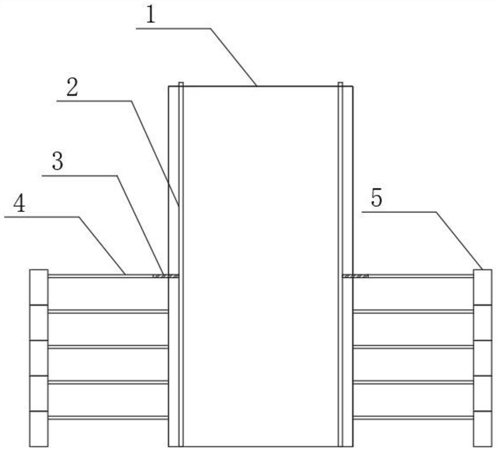
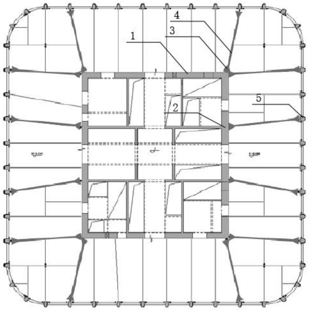
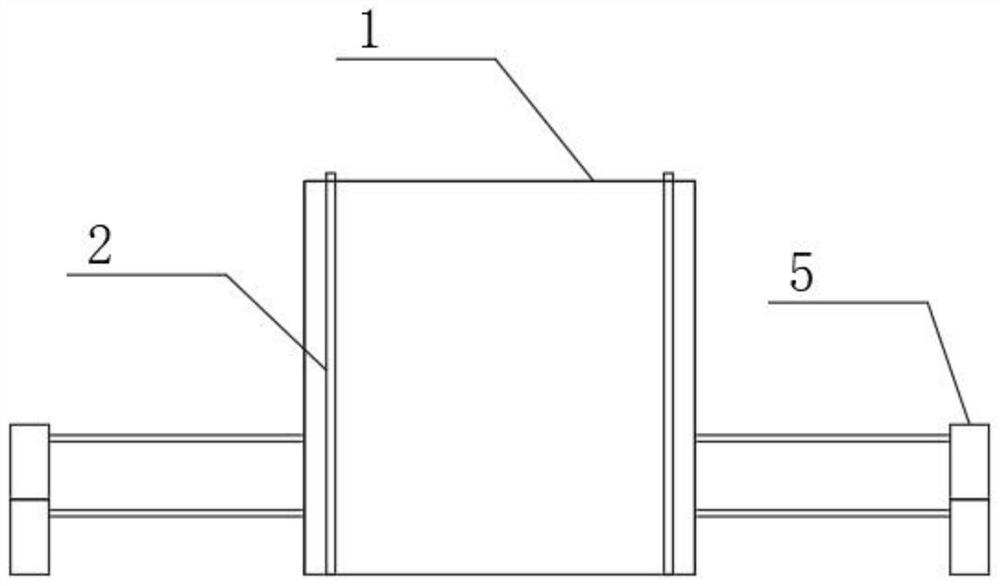
[0028] Such as Figure 1-8 As shown, the present invention provides a technical solution: a frame core tube rigidly connected to the floor beam structure system, including a core tube structure 1, a rigid steel column structure 2, a reserved corbel structure 3, and a rigidly connected floor beam structure 4. The outer frame column structure 5, the rigidly connected floor beam structure 4 is arranged between the core tube structure 1 and the outer frame column structure 5, and the rigidly connected floor beam structure 4 is rigidly connected to the core tube structure 1 and the outer frame column structure 5 respectively. connection, the rigidly connected floor beam structure 4 and the reserved corbel structure 3 are hingedly connected, and the present invention adopts several layers of rigidly connected floor beams with limited stiffness contribution to be respectively connected to the core tube structure 1 and the outer frame column structure 5 Rigid connection, in order to a...


PUM


Abstract

The invention provides a frame core tube rigid connection floor beam structure system and a construction method, and relates to the technical field of structure construction. The frame core tube rigid connection floor beam structure system comprises a core tube structure, a stiff steel column structure, a reserved bracket structure, a rigid connection floor beam structure and an outer frame column structure; a plurality of layers of rigid connection floor beams with limited rigidity contribution are arranged to be in rigid connection with a core tube structure and an outer frame column structure correspondingly, so that the purpose of cooperating with an outer frame and a core tube to work together is achieved, and the requirement for the overall stability of the structure is met. Then outer frame columns are installed, then rigid connection floor beams are installed, one end of a rigid connection floor beam structure is in rigid connection with the outer frame columns, the other end of the rigid connection floor beam structure is hinged to the reserved brackets, after overall construction of the frame core tube structure is completed, rear rigid connection construction is conducted, and reserved steel beams are welded to flanges and webs of the rigid connection floor beams; therefore, the influence of differential deformation between the core tube and the outer frame is eliminated or weakened.

Description

technical field [0001] The invention relates to the technical field of structural construction, in particular to a structural system and a construction method of a frame core tube rigidly connected to floor beams. Background technique [0002] In order to enhance the ability of the super high-rise frame core tube structure to cope with horizontal loads such as wind loads and earthquake loads, outrigger trusses and belt truss strengthening layers are usually arranged along one or several floors along the height, and outrigger trusses and ring belt truss reinforcement layers are arranged along the height, and outrigger trusses are arranged between the outer frame columns and the core tube. Arm truss, its principle is to increase the axial force of the outer frame column under the action of horizontal load, so as to increase the overturning moment that the frame column can bear, and reduce the lateral displacement of the structure; The truss is similar, but with the continuous ...

Claims


Application Information

Patent Timeline
Patent Type & Authority Applications(China)
IPC IPC(8): E04B1/19E04C3/02E04C3/32E04C3/30E04B1/38E04B1/58E04G21/00
CPCE04B1/19E04C3/02E04C3/32E04C3/30E04B1/38E04B1/58E04G21/00
Inventor 李健强王博杨勋滕洪园沈仁菊胡萌萌王帅谭江蜀程谦单宏亮张松波徐继贺
Owner CHINA CONSTR THIRD ENG BUREAU GRP CO LTD
Learn More