
Automatic overturning type frame alkali washing jig

A technology of automatic flipping and frame, applied in the direction of electrical components, circuits, semiconductor devices, etc., to achieve the effect of saving man-hours, neat appearance and stable structure

Pending Publication Date: 2022-03-04
江苏正芯电子科技有限公司
View PDF0 Cites 0 Cited by
  • Summary
  • Abstract
  • Description
  • Claims
  • Application Information

AI Technical Summary

Problems solved by technology

[0011] The purpose of the present invention is to provide an automatic flip-type frame alkali cleaning tool to solve the technical problem in the prior art that the SMD diode frame cannot be placed on the front and back sides with high efficiency alkali cleaning

Method used


Image

  • Automatic overturning type frame alkali washing jig
  • Automatic overturning type frame alkali washing jig
  • Automatic overturning type frame alkali washing jig

Examples


Embodiment 1

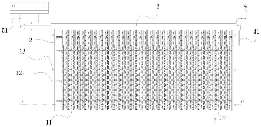
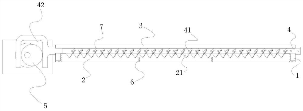
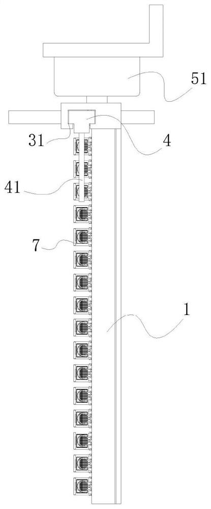
[0037] This embodiment provides an automatic flip-type frame alkali cleaning treatment tool, which includes a closed-loop frame, and a positioning straight plate 2 is arranged inside the frame, and several V-shaped positioning grooves 21 are evenly arranged on the upper end surface of the positioning straight plate 2, and one side of the frame is provided with There is a guide rail 3, and the guide rail 3 is provided with a T-shaped guide groove 31 with an opening facing the positioning straight plate 2. The T-shaped guide groove 31 is parallel to the positioning straight plate 2, and the T-shaped guide groove 31 is provided with a slidingly fitted T-shaped slide bar 4, T The outer surface of the shape slide bar 4 is horizontally provided with a material shifting rod 41 corresponding to the V-shaped positioning groove 21, the material shifting rod 41 is corresponding to the neutral position of the V-shaped positioning groove 21, and the horizontal height of the material shifting...

Embodiment 2

[0040] This embodiment provides an automatic flip-type frame alkali cleaning treatment tool, which includes a closed-loop frame, and a positioning straight plate 2 is arranged inside the frame, and several V-shaped positioning grooves 21 are evenly arranged on the upper end surface of the positioning straight plate 2, and one side of the frame is provided with There is a guide rail 3, and the guide rail 3 is provided with a T-shaped guide groove 31 with an opening facing the positioning straight plate 2. The T-shaped guide groove 31 is parallel to the positioning straight plate 2, and the T-shaped guide groove 31 is provided with a slidingly fitted T-shaped slide bar 4, T The outer surface of the shape slide bar 4 is horizontally provided with a material shifting rod 41 corresponding to the V-shaped positioning groove 21, the material shifting rod 41 is corresponding to the neutral position of the V-shaped positioning groove 21, and the horizontal height of the material shifting...


PUM


Abstract

The automatic overturning type frame alkali washing jig comprises a frame, a positioning straight plate is arranged in the frame, a plurality of V-shaped positioning grooves are evenly distributed in the upper end face of the positioning straight plate, a guide rail is arranged on one side of the frame, a T-shaped guide groove with an opening facing the positioning straight plate is formed in the guide rail, and the T-shaped guide groove is parallel to the positioning straight plate. A T-shaped sliding strip is arranged in the T-shaped guide groove in a sliding fit mode, a material stirring rod corresponding to the V-shaped positioning groove is horizontally arranged on the outer surface of the T-shaped sliding strip, the horizontal height of the material stirring rod is larger than that of the upper end face of the positioning straight plate, a U-shaped groove with an opening in the vertical direction is formed in one end of the T-shaped sliding strip, a matched cam is arranged in the U-shaped groove, and through the V-shaped positioning groove, the cam, the T-shaped sliding strip and the material stirring rod, the material stirring rod can rotate around the V-shaped positioning groove. The overturning of the SMD diode frame in the V-shaped positioning groove is realized, so that the technical effect of high-efficiency spraying and alkali washing on the front and back surfaces after one-time placement is met.

Description

technical field [0001] The invention belongs to the technical field of chip diode manufacturing, and in particular relates to an automatic flip-type frame alkali cleaning fixture. Background technique [0002] Due to its simple structure and high reliability, SMD diodes are widely used in important fields such as on-board electronic equipment and safety driving systems of fuel vehicles and new energy vehicles. In order to meet the development requirements of the continuous improvement of automobile quality and safety, various car manufacturers have put forward higher requirements for the dimensional accuracy and reliability of SMD diodes for automobiles. [0003] At present, the production process of SMD diodes for automobiles is as follows: [0004] The first step is to place the diode frame on the carrier plate for positioning, place the positioning cover on the lead frame, spot solder paste on the lead frame substrate, assemble the chip, spot solder paste on the chip, sp...

Claims


Application Information

Patent Timeline
Patent Type & Authority Applications(China)
IPC IPC(8): H01L33/48H01L33/00H01L21/02
CPCH01L33/48H01L33/00H01L21/02041
Inventor 黄永
Owner 江苏正芯电子科技有限公司
Learn More