Turbine housing having low-stress connecting flange and exhaust turbine having such turbine housing

A technology of turbine casing and exhaust turbine, which is applied to machines/engines, gas turbine devices, mechanical equipment, etc. Effects of extended service life, low transient thermal stress

Pending Publication Date: 2022-03-04
TURBO SYST SWITZERLAND LTD
View PDF3 Cites 0 Cited by
  • Summary
  • Abstract
  • Description
  • Claims
  • Application Information

AI Technical Summary

Problems solved by technology

Higher transient thermal stresses in turn lead to reduced lifetime of the turbine housing and thus of the entire turbocharger

Method used


Image

  • Turbine housing having low-stress connecting flange and exhaust turbine having such turbine housing
  • Turbine housing having low-stress connecting flange and exhaust turbine having such turbine housing
  • Turbine housing having low-stress connecting flange and exhaust turbine having such turbine housing

Examples


Embodiment Construction

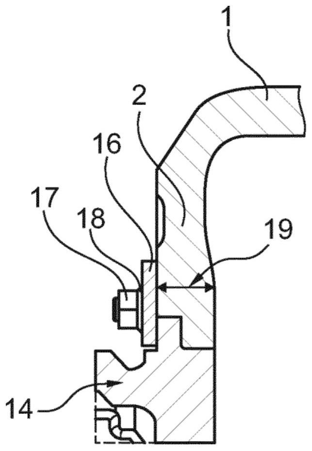
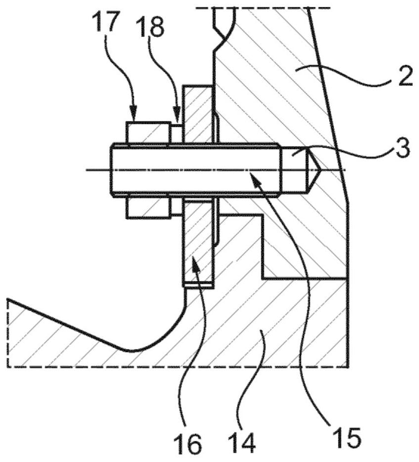
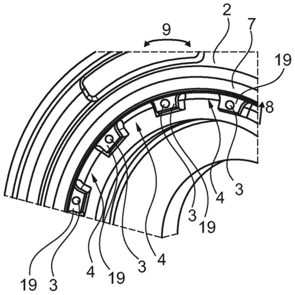
[0040] image 3 A sketch for illustrating a turbine housing according to the invention is shown, where in image 3Only a partial area of ​​the turbine housing is shown in . The turbine housing has a connecting flange 2 arranged coaxially to the longitudinal center axis of the turbine housing, which is equipped with a clamping edge 7 . In the clamping edge 7 there is provided a connecting web 19 extending inwardly in the radial direction 8 , into which the housing connecting hole 3 is introduced. The mentioned connection webs 19 and the housing connection openings 3 inserted therein are spaced apart from one another in the circumferential direction 9 of the turbine housing. The connection lugs and the housing connection openings are arranged along one or more circles in the circumferential direction 9 in the connection flange. Between every two housing connection openings 3 spaced apart from one another in the circumferential direction 9 , a material recess 4 which is open r...


PUM


Abstract

The invention relates to a turbine housing for an exhaust turbine, having a connecting flange for coupling to a bearing housing on the bearing housing side, in which connecting flange housing connecting bores spaced apart from one another in the circumferential direction are provided, wherein a material recess, which is open radially inward in the direction of the longitudinal center axis of the turbine housing, is provided in the connecting flange between adjacent housing connecting bores. The invention also relates to an exhaust turbine equipped with such a turbine housing.

Description

technical field [0001] The invention relates to a turbine housing with a low-stress connecting flange and to an exhaust gas turbine with such a turbine housing. According to an embodiment, the exhaust gas turbine may eg be a turbocharger turbine or a power turbine for a turbocharger. Background technique [0002] A one-piece exhaust system for a gas turbine is known from US 2015 / 0143814 A1. The exhaust system has a turbine outlet housing and a turbine exhaust manifold, wherein the turbine outlet housing is connected to the turbine exhaust manifold at an outwardly directed connection flange. This makes it possible, if necessary, to detach the turbine exhaust manifold from the turbine outlet housing by simple decoupling and to replace it with a new component. [0003] A gas turbine is known from EP 3 103 972 A1, in which the high-pressure turbine housing is connected to the diffuser housing at an outwardly directed flange. [0004] A turbocharger is known from EP 1 273 760 ...

Claims


Application Information

Patent Timeline
Patent Type & Authority Applications(China)
IPC IPC(8): F01D25/24F01D5/04F02C6/12F01D25/16F01D21/04
CPCF01D25/243F01D5/04F05D2260/972F05D2240/15F01D25/16F01D21/045F01D25/24F05D2260/31F05D2260/39F01D25/162F05D2220/40F05D2240/14
Inventor 马赛厄斯·里奇纳
Owner TURBO SYST SWITZERLAND LTD
Why Eureka
Try Eureka