
Roller type quilt rolling machine for agricultural greenhouse

A quilt rolling machine and roller type technology used in the field of agricultural greenhouses

Pending Publication Date: 2022-03-08
BEIJING GUANGHUA TEXTILE GRP +3
View PDF5 Cites 1 Cited by
  • Summary
  • Abstract
  • Description
  • Claims
  • Application Information

AI Technical Summary

Problems solved by technology

[0004] In order to solve the defects and deficiencies existing in the existing agricultural greenhouse roll-up machines, a roll-type roll-type quilter for agricultural greenhouses is provided. The invention solves many problems existing in the existing roll-up machines

Method used


Image

  • Roller type quilt rolling machine for agricultural greenhouse
  • Roller type quilt rolling machine for agricultural greenhouse

Examples


Embodiment 1

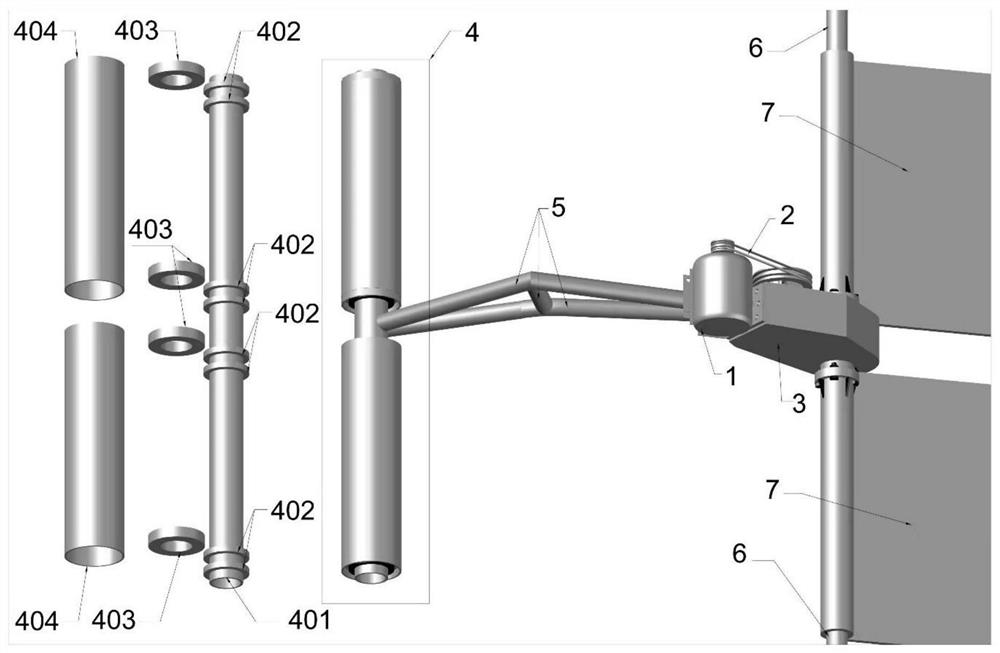
[0036] Such as figure 1 As shown, a roll-type quilt rolling machine for agricultural greenhouses, including a motor 1, a transmission part 2, a reducer 3, a support roller set 4, a support connector 5, a roll quilt rod 6 and a quilt 7, does not contain roll cotton The quilt rod 6 and the quilt 7 are the roll quilt host; the motor 1 drives the reducer 3 to work through the transmission part 2, and the rear end of the reducer 3 is connected to the support roller set 4 through the connecting plate and the support connector 5, and the reducer 3 The inside of the front end intersects with the roll quilt rod 6, and the 7 rolls of quilt are placed on the roll quilt rod 6; the motor 1 drives the reducer 3 through the transmission part 2, and the reducer 3 drives the roll quilt rod 6 through the intersecting connection part The rotation of finishing cotton-wadded quilt 7 is put.

[0037] The length of the rolled quilt rod 6 in this embodiment is 60-80 meters, and the support roller se...

Embodiment 2

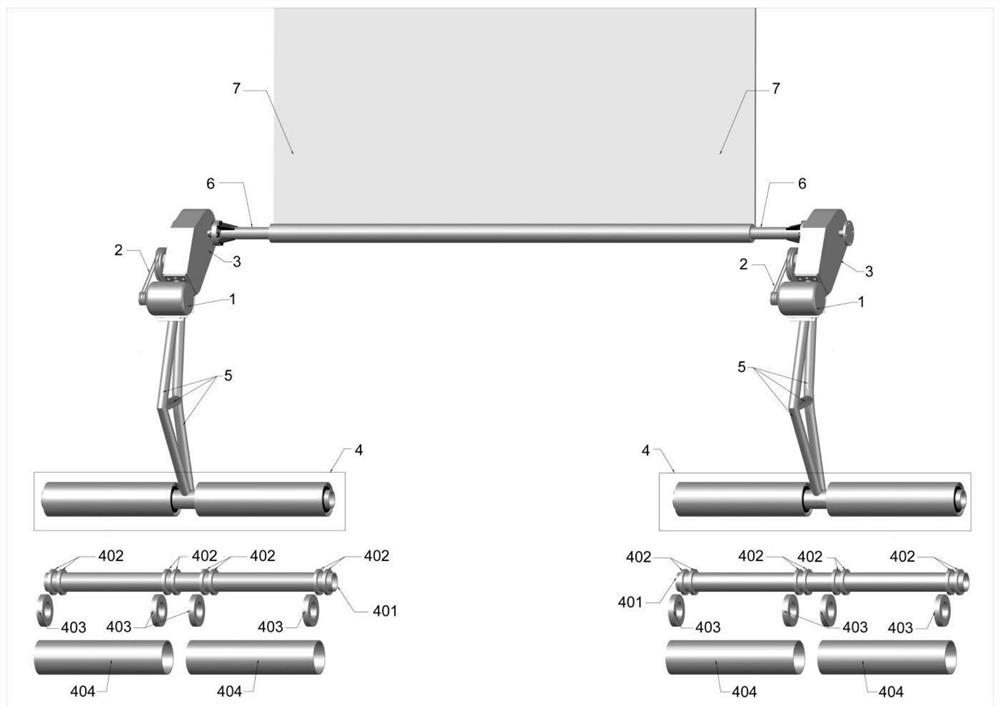
[0044] Such as figure 2 As shown, a roll-type quilt rolling machine for agricultural greenhouses, including a motor 1, a transmission part 2, a reducer 3, a support roller set 4, a support connector 5, a roll quilt rod 6 and a quilt 7, does not contain roll cotton The quilt rod 6 and the quilt 7 are the roll quilt host; the motor 1 drives the reducer 3 to work through the transmission part 2, and the rear end of the reducer 3 is connected to the support roller set 4 through the connecting plate and the support connector 5, and the reducer 3 The inside of the front end intersects with the roll quilt rod 6, and the 7 rolls of quilt are placed on the roll quilt rod 6; the motor 1 drives the reducer 3 through the transmission part 2, and the reducer 3 drives the roll quilt rod 6 through the intersecting connection part The rotation of finishing cotton-wadded quilt 7 is put.

[0045] The length of the rolled quilt rod 6 in this embodiment is 110-130 meters, and the support roller...


PUM


Abstract

A roller type quilt rolling machine for an agricultural greenhouse comprises a motor, a transmission part, a speed reducer, a quilt rolling rod and a quilt, the roller type quilt rolling machine further comprises a supporting roller sleeve part and a supporting connecting part, and the quilt rolling machine without the quilt rolling rod and the quilt is a quilt rolling main machine; the supporting roller set comprises two hollow rollers with the same specification and size, four or six or eight bearings and bearing limiting pieces and a center shaft. When two cotton quilts are rolled and unrolled on the cotton quilt rolling rod, the speed reducer of one quilt rolling main machine is used for being installed on the cotton quilt rolling rod between the two cotton quilts, and when one cotton quilt is rolled and unrolled on the cotton quilt rolling rod, the speed reducers of the two quilt rolling main machines are used for being installed on the cotton quilt rolling rods at the two ends of one cotton quilt respectively. The motor drives the speed reducer through the transmission piece, and the speed reducer drives the cotton quilt rolling rod to rotate through the intersecting connection portion of the speed reducer and the cotton quilt rolling rod to complete rolling and unrolling of the cotton quilt. The problems that an existing quilt rolling machine is prone to unbalance and inclination, high in cost, difficult to maintain, not suitable for being applied to large-span agricultural greenhouses and the like are solved.

Description

technical field [0001] The invention relates to the technical field of agricultural greenhouses, in particular to a roll-type quilter for agricultural greenhouses. Background technique [0002] Most of the existing agricultural greenhouse roll-up machines adopt the method of vertical long rod and large swing long rod (herringbone), and the large swing long rod and vertical rod are connected by pin shafts. This connection form is suitable for greenhouses with small spans. For greenhouses, once the span of the greenhouse is increased, the rod will be lengthened, and the slenderness ratio will be increased, and the rolling rod will be deformed when subjected to a small external force (wind), and once deformed, it will affect the overall quilt rolling; the other is The hanging rail connection requires welding a very long and high structure. In order to stabilize the structure, the production of the structure is complicated, and the shape-finding design of different shapes of gre...

Claims


Application Information

Patent Timeline
IPC IPC(8): A01G9/22B65H75/44
CPCA01G9/222B65H75/4486Y02A40/25
Inventor 程庆宝杜以杰陈晓伟白飞飞黄学军
Owner BEIJING GUANGHUA TEXTILE GRP
Learn More