An oil sludge treatment method suitable for heavy bottom oil sludge and clear tank oil sludge

A base oil, heavy-duty technology, used in sludge treatment, water/sludge/sewage treatment, dehydration/drying/concentrated sludge treatment, etc., can solve the problems of inaccurate pH measurement, easy deposition of sludge, and poor fluidity. , to achieve the effect of not producing dust hazards, solving unsmooth discharge, and improving the flow field state

Active Publication Date: 2022-07-19
西安德兴环保科技有限公司
View PDF10 Cites 0 Cited by
  • Summary
  • Abstract
  • Description
  • Claims
  • Application Information

AI Technical Summary

Problems solved by technology

At present, most enterprises treat the oily scum in the sewage treatment plant and the oily sludge at the bottom of the adjustment pool, or mechanically dehydrate it and then enter the coking unit, or use traditional simple sedimentation and centrifugation with unsatisfactory results, and then hand it over to a qualified treatment unit. co-processing
The current oil sludge treatment technology has a better effect on the treatment of scum in the sewage treatment plant, sludge at the bottom of the adjustment tank and activated sludge, and sludge at the bottom of the light oil tank area. The heavy bottom sludge in the oil tank area contains a large amount of colloid, asphaltene and other components, and has a high viscosity. The existing treatment technology has the following problems in the operation process, which makes the equipment unable to operate normally: 1. Recombination in the sludge Partially adhered to the pH probe, resulting in inaccurate pH measurement or damage to the pH meter, which affects the normal operation of the system; 2. The bottom of the sludge separation device is prone to deposit sludge, which blocks the drainage pipe, affecting the continuous and stable operation of the device; 3. Discharge of the dry sludge bin There are often cases of poor unloading
As for the clear tank sludge, it has a strong odor and is sticky, and on the basis of the properties of the heavy bottom sludge, it also has the characteristics of high oil content, high solid content, low water content, poor fluidity or even basically no fluidity. , the existing technology is unable to deal with it

Method used


Image

  • An oil sludge treatment method suitable for heavy bottom oil sludge and clear tank oil sludge
  • An oil sludge treatment method suitable for heavy bottom oil sludge and clear tank oil sludge
  • An oil sludge treatment method suitable for heavy bottom oil sludge and clear tank oil sludge

Examples


Embodiment 1

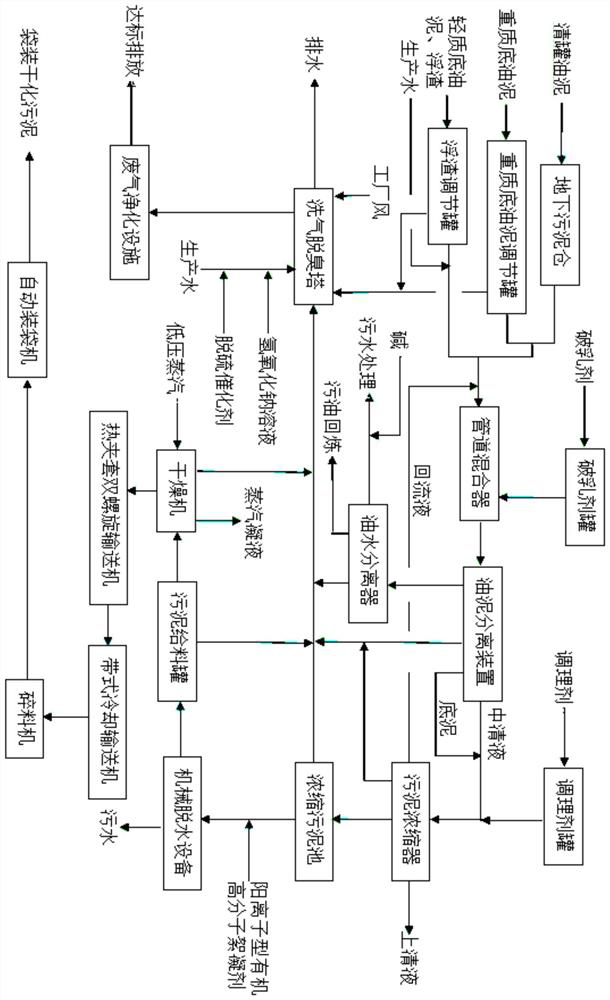
[0078] Add 10m in the heavy bottom sludge conditioning tank of Example 1 3 Heavy bottom sludge S 1 , S 1 ’, add 15m to the scum regulating tank 3 Scum S 2 , maintain the temperature in the two regulating tanks at 40 ℃ by means of steam coil, and transport them to the sludge separation device by pump respectively, and add 98% concentrated sulfuric acid at the same time. After adjusting the pH of the sludge separation device to 1.5, stop adding acid, and the sludge separation device Set the heat preservation, stand and separate at 40°C for 72 hours.

[0079] The recovered slop oil S is extracted from the upper part of the sludge separation device 0 , and then all the clear liquid in the middle part of the sludge separation device and the bottom sludge in the lower part are discharged into the sludge thickener and then sample S 3 , S 3 ’, add 30% sodium hydroxide solution to the sludge thickener to adjust the pH to 7. 0 , S 1 , S 2 , S 3 The analysis is carried out, and...

Embodiment 2

[0096] Take the bottom sludge from a crude oil tank farm of a petrochemical enterprise, and the solid content of the bottom sludge is 8.21%, the oil content is 31.65% (the light oil content is 5.34%), and the water content is 60.14%. 200 g of the bottom sludge was put into a 1000 mL separatory funnel, then 400 mL of distilled water was added to the separatory funnel, and 98% sulfuric acid was added to the separatory funnel, and the pH was adjusted to 2 after shaking. After the separatory funnel was kept at a constant temperature in a 40°C water bath for 72 hours, all the mud-water mixture in the lower part of the separatory funnel was discharged into the graduated cylinder. Therefore, the recovery rate of light oil is: (200×5.34%-580×0.16%) / (200×5.34%)=91.31%.

Embodiment 3

[0098] Take the cleaned oil sludge from a petrochemical enterprise, the solid content of the cleaned oil sludge is 25.7%, the oil content is 30% (the light oil content is 4.86%), and the water content is 44.3%. Put 200 g of the clear oil sludge into a 1000 mL separatory funnel, then add 400 mL of distilled water to the separatory funnel, add 98% sulfuric acid to the separatory funnel, and adjust the pH to 2 after shaking. After the separatory funnel was kept at a constant temperature in a 40°C water bath for 72 hours, all the mud-water mixture in the lower part of the separatory funnel was discharged into the graduated cylinder. Therefore, the recovery rate of light oil is: (200×4.86%-583×0.12%) / (200×4.86%)=92.8%.


PUM

PropertyMeasurementUnit
solid contentaaaaaaaaaa

Abstract

The invention provides an oily sludge treatment method suitable for heavy bottom oily sludge and clear tank oily sludge, which optimizes the heavy oily sludge before the oily sludge is separated, so as to ensure that the oily sludge is sufficiently mixed with a demulsifier before demulsification and separation. The mixing is uniform, and the pH measurement method is redesigned to facilitate the control system to be in a stable pH value range, and the closed-loop nature of the process line of the entire treatment process is redesigned to reduce the initial investment cost and energy consumption rate of the entire process method. In addition, a gravity type sludge separation device is also proposed, which includes a vertical cylinder, a guide cylinder arranged in the vertical cylinder, and an sludge feed component, a light sewage oil discharge component, and a clear liquid discharge component. and sediment effluent components.

Description

technical field [0001] The invention relates to the technical field of harmless treatment of oily sludge in oil fields and petrochemical industries, in particular to an oily sludge treatment method suitable for heavy bottom oily sludge and tank cleaning sludge. Background technique [0002] Oil sludge is one of the main pollutants produced in the process of storage, transportation and refining of oil products. It contains a lot of odorous toxic substances such as benzene series, phenols, fenugreek, pyrene, etc. The composition is complex and belongs to hazardous waste. It is listed as HW08 hazardous waste in the "National Hazardous Waste List". [0003] According to incomplete statistics, the total amount of oily sludge produced in my country is more than 5 million tons each year, and with the deep exploitation of most oil fields, the output of oily sludge will continue to increase. The composition of sludge is extremely complex, and its composition varies greatly depending...

Claims


Application Information

Patent Timeline
Patent Type & Authority Patents(China)
IPC IPC(8): C02F11/00C02F11/14C02F11/121C02F11/13C02F9/04C02F103/36
CPCC02F11/00C02F11/14C02F11/143C02F11/145C02F11/147C02F11/121C02F11/13C02F1/40C02F1/66C02F2303/02C02F2209/06C02F2103/365
Inventor 罗德春
Owner 西安德兴环保科技有限公司
Why Eureka
Try Eureka